
How to Use AD584 - Pin Programmable Precision Voltage Reference: Examples, Pinouts, and Specs
 Design with AD584 - Pin Programmable Precision Voltage Reference in Cirkit Designer
Introduction
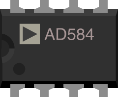
The AD584 is a precision voltage reference manufactured by Analog Devices (Part ID: AD584JNZ). It provides stable and accurate output voltages that can be programmed using external pins. This component is ideal for applications requiring high accuracy, low temperature drift, and long-term stability. The AD584 is commonly used in analog-to-digital converters (ADCs), digital-to-analog converters (DACs), calibration systems, and precision measurement equipment.
Explore Projects Built with AD584 - Pin Programmable Precision Voltage Reference
 Open Project in Cirkit Designer
 Open Project in Cirkit Designer
 Open Project in Cirkit Designer
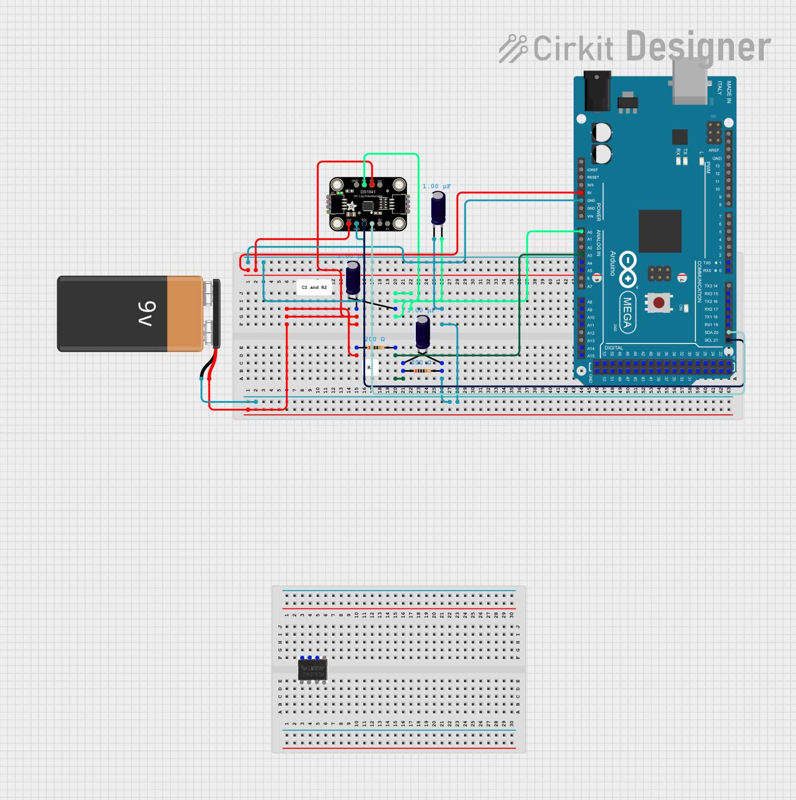 Open Project in Cirkit Designer
Explore Projects Built with AD584 - Pin Programmable Precision Voltage Reference
Open Project in Cirkit DesignerOpen Project in Cirkit DesignerOpen Project in Cirkit DesignerOpen Project in Cirkit DesignerCommon Applications:
- Analog and digital instrumentation
- Calibration and test equipment
- Precision voltage sources for ADCs and DACs
- High-accuracy measurement systems
Technical Specifications
Key Technical Details:
- Input Voltage Range: 4.5V to 30V
- Output Voltage Options: 2.5V, 5V, 7.5V, and 10V (programmable via pins)
- Output Current: Up to 10mA
- Initial Accuracy: ±0.14% (typical for AD584JNZ)
- Temperature Coefficient: 25 ppm/°C (typical)
- Output Noise: 100 µV peak-to-peak (0.1 Hz to 10 Hz)
- Operating Temperature Range: 0°C to +70°C (for AD584JNZ)
- Package Type: 8-pin PDIP (Plastic Dual In-line Package)
Pin Configuration and Descriptions:
The AD584 is an 8-pin device. The table below describes each pin:
| Pin Number | Pin Name | Description |
|---|---|---|
| 1 | VOUT | Output voltage pin. Provides the selected reference voltage (2.5V, 5V, 7.5V, 10V). |
| 2 | GND | Ground pin. Connect to the circuit ground. |
| 3 | VSET | Voltage programming pin. Connect to GND or VOUT to select the desired output voltage. |
| 4 | NC | No connection. Leave this pin unconnected. |
| 5 | NC | No connection. Leave this pin unconnected. |
| 6 | VIN | Input voltage pin. Connect to a DC voltage source (4.5V to 30V). |
| 7 | TEMP | Temperature compensation pin. Typically left unconnected. |
| 8 | VSET | Voltage programming pin. Connect to GND or VOUT to select the desired output voltage. |
Voltage Programming Table:
The output voltage of the AD584 is determined by the connections to the VSET pins (Pins 3 and 8). The table below shows the configuration:
| VSET Pin 3 | VSET Pin 8 | Output Voltage |
|---|---|---|
| GND | GND | 2.5V |
| GND | VOUT | 5.0V |
| VOUT | GND | 7.5V |
| VOUT | VOUT | 10.0V |
Usage Instructions
How to Use the AD584 in a Circuit:
- Power Supply: Connect a DC voltage source (4.5V to 30V) to the VIN pin (Pin 6). Ensure the input voltage is stable and within the specified range.
- Ground Connection: Connect the GND pin (Pin 2) to the circuit ground.
- Output Voltage Selection: Configure the VSET pins (Pins 3 and 8) according to the desired output voltage, as shown in the Voltage Programming Table.
- Output Connection: Connect the VOUT pin (Pin 1) to the load or circuit requiring the reference voltage. Ensure the load does not exceed the maximum output current of 10mA.
Important Considerations:
- Use decoupling capacitors (e.g., 0.1µF ceramic capacitor) between VIN and GND to reduce noise and improve stability.
- Avoid exceeding the maximum input voltage (30V) to prevent damage to the device.
- Ensure proper thermal management if operating at higher input voltages or output currents.
- For best accuracy, minimize external noise and temperature variations in the operating environment.
Example: Using AD584 with Arduino UNO
The AD584 can be used as a precision voltage reference for ADC calibration in an Arduino UNO project. Below is an example of how to connect and use the AD584:
Circuit Connections:
- Connect VIN (Pin 6) to the Arduino's 5V pin.
- Connect GND (Pin 2) to the Arduino's GND pin.
- Configure the VSET pins (Pins 3 and 8) for the desired output voltage (e.g., 5V).
- Connect VOUT (Pin 1) to an analog input pin on the Arduino (e.g., A0).
Arduino Code Example:
// Example: Reading the AD584 output voltage using Arduino UNO
const int referencePin = A0; // Analog pin connected to AD584 VOUT
float referenceVoltage = 5.0; // Expected output voltage of AD584 (e.g., 5V)

void setup() {
  Serial.begin(9600); // Initialize serial communication
  analogReference(DEFAULT); // Use default 5V reference for ADC
}

void loop() {
  int adcValue = analogRead(referencePin); // Read ADC value from AD584
  float voltage = (adcValue / 1023.0) * referenceVoltage;
  // Convert ADC value to voltage

  Serial.print("Measured Voltage: ");
  Serial.print(voltage, 3); // Print voltage with 3 decimal places
  Serial.println(" V");

  delay(1000); // Wait 1 second before next reading
}
Notes:
- Adjust the
referenceVoltagevariable in the code if using a different output voltage from the AD584. - Ensure the Arduino's ADC reference voltage matches the AD584's output voltage for accurate readings.
Troubleshooting and FAQs
Common Issues and Solutions:
No Output Voltage:
- Verify the input voltage is within the specified range (4.5V to 30V).
- Check the connections to the VSET pins to ensure proper configuration.
- Ensure the load connected to VOUT does not exceed 10mA.
Inaccurate Output Voltage:
- Confirm the input voltage is stable and free from noise.
- Use decoupling capacitors to reduce noise and improve stability.
- Verify the temperature of the operating environment is within the specified range (0°C to +70°C for AD584JNZ).
Overheating:
- Check for excessive input voltage or output current.
- Ensure proper thermal management and ventilation.
FAQs:
Q: Can the AD584 be used with a 3.3V system?
A: No, the minimum input voltage for the AD584 is 4.5V. It is not suitable for 3.3V systems.Q: What is the maximum load current the AD584 can drive?
A: The AD584 can drive a maximum load current of 10mA.Q: Can I leave the unused pins unconnected?
A: Yes, the NC (No Connection) pins can be left unconnected. The TEMP pin is also typically left unconnected unless temperature compensation is required.Q: How do I improve the accuracy of the AD584?
A: Use a stable input voltage, minimize noise, and operate the device within the recommended temperature range.
This concludes the documentation for the AD584 - Pin Programmable Precision Voltage Reference.