Cirkit Designer Logo
Cirkit Designer
Your all-in-one circuit design IDE
Home / 
Component Documentation

How to Use rx5808: Examples, Pinouts, and Specs

Image of rx5808
Cirkit Designer LogoDesign with rx5808 in Cirkit Designer

Introduction

The RX5808 is a low-power, high-performance RF receiver module designed for wireless communication in the 433MHz to 915MHz frequency range. It is widely used in remote control systems, telemetry applications, and other wireless data transmission projects. The RX5808 is known for its compact size, ease of integration with microcontrollers, and reliable performance, making it a popular choice for hobbyists and professionals alike.

Explore Projects Built with rx5808

Use Cirkit Designer to design, explore, and prototype these projects online. Some projects support real-time simulation. Click "Open Project" to start designing instantly!
Satellite-Based Timing and Navigation System with SDR and Atomic Clock Synchronization
Image of GPS 시스템 측정 구성도_Confirm: A project utilizing rx5808 in a practical application
This circuit appears to be a complex system involving power supply management, GPS and timing synchronization, and data communication. It includes a SI-TEX G1 Satellite Compass for GPS data, an XHTF1021 Atomic Rubidium Clock for precise timing, and Ettus USRP B200 units for software-defined radio communication. Power is supplied through various SMPS units and distributed via terminal blocks and DC jacks. Data communication is facilitated by Beelink MINI S12 N95 computers, RS232 splitters, and a 1000BASE-T Media Converter for network connectivity. RF Directional Couplers are used to interface antennas with the USRP units, and the entire system is likely contained within cases for protection and organization.
Cirkit Designer LogoOpen Project in Cirkit Designer
Arduino UNO with 433MHz RF Module for Wireless Communication
Image of Receiver: A project utilizing rx5808 in a practical application
This circuit consists of an Arduino UNO connected to an RXN433MHz radio frequency module. The Arduino provides 5V power and ground to the RF module and is configured to communicate with it via digital pin D11. Additionally, a multimeter is connected with alligator clip cables to measure the voltage supplied to the RF module.
Cirkit Designer LogoOpen Project in Cirkit Designer
Satellite Compass and Network-Integrated GPS Data Processing System
Image of GPS 시스템 측정 구성도_241016: A project utilizing rx5808 in a practical application
This circuit comprises a satellite compass, a mini PC, two GPS antennas, power supplies, a network switch, media converters, and an atomic rubidium clock. The satellite compass is powered by a triple output DC power supply and interfaces with an RS232 splitter for 1PPS signals. The mini PCs are connected to the USRP B200 devices via USB for data and power, and to media converters via Ethernet, which in turn connect to a network switch using fiber optic links. The antennas are connected to the USRP B200s through RF directional couplers, and the atomic clock provides a 1PPS input to the RS232 splitter.
Cirkit Designer LogoOpen Project in Cirkit Designer
Battery-Powered nRF52840 and HT-RA62 Communication Module
Image of NRF52840+HT-RA62: A project utilizing rx5808 in a practical application
This circuit is a wireless communication system powered by a 18650 Li-ion battery, featuring an nRF52840 ProMicro microcontroller and an HT-RA62 transceiver module. The nRF52840 handles the control logic and interfaces with the HT-RA62 for data transmission, while the battery provides the necessary power for the entire setup.
Cirkit Designer LogoOpen Project in Cirkit Designer

Explore Projects Built with rx5808

Use Cirkit Designer to design, explore, and prototype these projects online. Some projects support real-time simulation. Click "Open Project" to start designing instantly!
Image of GPS 시스템 측정 구성도_Confirm: A project utilizing rx5808 in a practical application
Satellite-Based Timing and Navigation System with SDR and Atomic Clock Synchronization
This circuit appears to be a complex system involving power supply management, GPS and timing synchronization, and data communication. It includes a SI-TEX G1 Satellite Compass for GPS data, an XHTF1021 Atomic Rubidium Clock for precise timing, and Ettus USRP B200 units for software-defined radio communication. Power is supplied through various SMPS units and distributed via terminal blocks and DC jacks. Data communication is facilitated by Beelink MINI S12 N95 computers, RS232 splitters, and a 1000BASE-T Media Converter for network connectivity. RF Directional Couplers are used to interface antennas with the USRP units, and the entire system is likely contained within cases for protection and organization.
Cirkit Designer LogoOpen Project in Cirkit Designer
Image of Receiver: A project utilizing rx5808 in a practical application
Arduino UNO with 433MHz RF Module for Wireless Communication
This circuit consists of an Arduino UNO connected to an RXN433MHz radio frequency module. The Arduino provides 5V power and ground to the RF module and is configured to communicate with it via digital pin D11. Additionally, a multimeter is connected with alligator clip cables to measure the voltage supplied to the RF module.
Cirkit Designer LogoOpen Project in Cirkit Designer
Image of GPS 시스템 측정 구성도_241016: A project utilizing rx5808 in a practical application
Satellite Compass and Network-Integrated GPS Data Processing System
This circuit comprises a satellite compass, a mini PC, two GPS antennas, power supplies, a network switch, media converters, and an atomic rubidium clock. The satellite compass is powered by a triple output DC power supply and interfaces with an RS232 splitter for 1PPS signals. The mini PCs are connected to the USRP B200 devices via USB for data and power, and to media converters via Ethernet, which in turn connect to a network switch using fiber optic links. The antennas are connected to the USRP B200s through RF directional couplers, and the atomic clock provides a 1PPS input to the RS232 splitter.
Cirkit Designer LogoOpen Project in Cirkit Designer
Image of NRF52840+HT-RA62: A project utilizing rx5808 in a practical application
Battery-Powered nRF52840 and HT-RA62 Communication Module
This circuit is a wireless communication system powered by a 18650 Li-ion battery, featuring an nRF52840 ProMicro microcontroller and an HT-RA62 transceiver module. The nRF52840 handles the control logic and interfaces with the HT-RA62 for data transmission, while the battery provides the necessary power for the entire setup.
Cirkit Designer LogoOpen Project in Cirkit Designer

Common Applications and Use Cases

  • Remote control systems (e.g., drones, RC cars, and planes)
  • Wireless telemetry for IoT devices
  • Data transmission in industrial automation
  • Wireless sensor networks
  • DIY electronics projects requiring RF communication

Technical Specifications

The RX5808 module is designed to provide stable and efficient RF communication. Below are its key technical specifications:

Parameter Value
Frequency Range 433MHz to 915MHz
Operating Voltage 5V DC
Current Consumption ~25mA
Sensitivity -90dBm to -105dBm (typical)
Modulation Type FM (Frequency Modulation)
Data Rate Up to 10kbps
Operating Temperature -20°C to +70°C
Dimensions 21mm x 12mm x 3mm

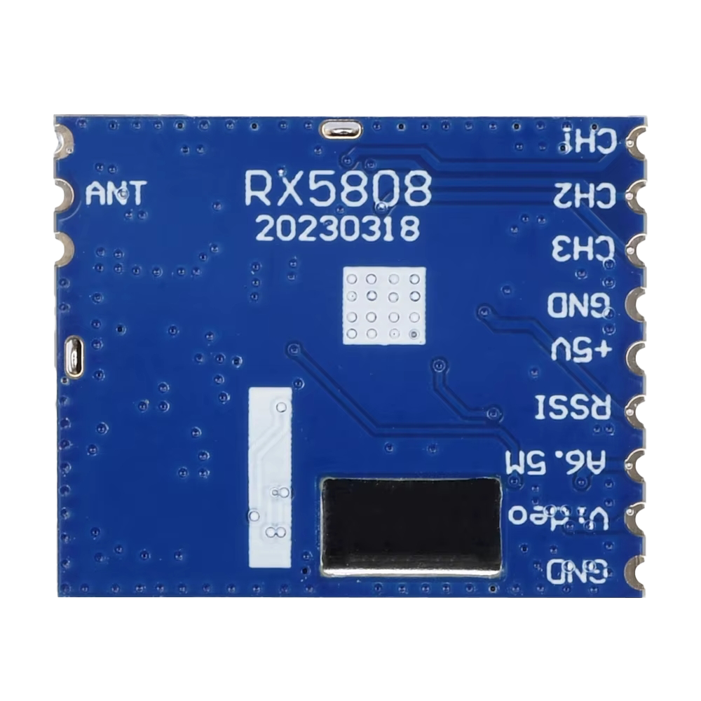
Pin Configuration and Descriptions

The RX5808 module typically has 8 pins. Below is the pinout and description:

Pin Number Pin Name Description
1 GND Ground connection
2 VCC Power supply (5V DC)
3 DATA Digital data output
4 CS Chip Select (active low)
5 CLK Clock input for SPI communication
6 MOSI Master Out Slave In (SPI data input)
7 MISO Master In Slave Out (SPI data output)
8 ANT Antenna connection for RF signal reception

Usage Instructions

The RX5808 module is straightforward to use and can be easily integrated into a circuit. Below are the steps and best practices for using the module:

Connecting the RX5808 to a Microcontroller

  1. Power Supply: Connect the VCC pin to a 5V power source and the GND pin to ground.
  2. SPI Communication: Connect the CS, CLK, MOSI, and MISO pins to the corresponding SPI pins on your microcontroller.
  3. Antenna: Attach a suitable antenna to the ANT pin to ensure optimal RF signal reception.
  4. Data Output: Use the DATA pin to receive the demodulated digital signal.

Example: Using RX5808 with Arduino UNO

Below is an example of how to interface the RX5808 with an Arduino UNO to receive RF data:

#include <SPI.h>

// Define RX5808 SPI pins
#define CS_PIN 10  // Chip Select pin
#define CLK_PIN 13 // Clock pin
#define MOSI_PIN 11 // Master Out Slave In
#define MISO_PIN 12 // Master In Slave Out

void setup() {
  // Initialize Serial Monitor for debugging
  Serial.begin(9600);

  // Initialize SPI communication
  SPI.begin();
  pinMode(CS_PIN, OUTPUT);
  digitalWrite(CS_PIN, HIGH); // Set CS pin to HIGH (inactive)

  Serial.println("RX5808 Initialized");
}

void loop() {
  // Example: Read data from RX5808
  digitalWrite(CS_PIN, LOW); // Activate RX5808
  byte receivedData = SPI.transfer(0x00); // Send dummy byte to receive data
  digitalWrite(CS_PIN, HIGH); // Deactivate RX5808

  // Print received data to Serial Monitor
  Serial.print("Received Data: ");
  Serial.println(receivedData, HEX);

  delay(100); // Small delay for stability
}

Important Considerations

  • Antenna Selection: Use an antenna tuned to the operating frequency range (e.g., 433MHz or 915MHz) for optimal performance.
  • Power Supply: Ensure a stable 5V power supply to avoid noise or instability in the RF signal.
  • SPI Configuration: Configure the SPI settings (e.g., clock speed) to match the RX5808's requirements.
  • Interference: Minimize interference from other RF devices operating in the same frequency range.

Troubleshooting and FAQs

Common Issues and Solutions

  1. No Data Received

    • Cause: Incorrect wiring or SPI configuration.
    • Solution: Double-check the connections and ensure the SPI pins are correctly assigned in the code.
  2. Weak Signal Reception

    • Cause: Poor antenna or interference from nearby devices.
    • Solution: Use a high-quality antenna and ensure the module is placed away from sources of interference.
  3. Module Overheating

    • Cause: Excessive current draw or improper power supply.
    • Solution: Verify the power supply voltage and current ratings. Ensure proper ventilation.
  4. Unstable Data Output

    • Cause: Noise in the power supply or RF interference.
    • Solution: Use decoupling capacitors near the power pins and reduce nearby RF noise sources.

FAQs

Q1: Can the RX5808 operate at 3.3V?
A1: No, the RX5808 requires a 5V power supply for proper operation.

Q2: What is the maximum range of the RX5808?
A2: The range depends on the antenna and environmental conditions but typically ranges from 100m to 500m in open areas.

Q3: Can I use the RX5808 for two-way communication?
A3: No, the RX5808 is a receiver module only. For two-way communication, you will need a transceiver module.

Q4: How do I improve signal reception?
A4: Use a properly tuned antenna, minimize interference, and ensure a clear line of sight between the transmitter and receiver.

By following this documentation, you can effectively integrate and troubleshoot the RX5808 module in your projects.