Cirkit Designer Logo
Cirkit Designer
Your all-in-one circuit design IDE
Home / 
Component Documentation

How to Use Arduino Due: Examples, Pinouts, and Specs

Image of Arduino Due
Cirkit Designer LogoDesign with Arduino Due in Cirkit Designer

Introduction

The Arduino Due is a powerful microcontroller board based on the Atmel SAM3X8E ARM Cortex-M3 CPU. As the first Arduino board to feature a 32-bit ARM core microcontroller, it represents a significant step up in capabilities from the traditional 8-bit microcontroller boards such as the Arduino Uno. The Due is ideal for projects that require more computational power, memory, and a variety of I/O interfaces, including applications in robotics, 3D printing, and complex sensor networks.

Explore Projects Built with Arduino Due

Use Cirkit Designer to design, explore, and prototype these projects online. Some projects support real-time simulation. Click "Open Project" to start designing instantly!
Arduino Uno R3-Based Voice-Controlled Robot with Servo Actuation and SD Logging
Image of wheel: A project utilizing Arduino Due in a practical application
This circuit features an Arduino Uno R3 as the central microcontroller, interfaced with a variety of components. It includes a voice recognition module for audio input commands, an analog thumbstick for manual control, and multiple servos for actuation. Additionally, the circuit integrates an I2C LCD screen for display purposes, an infrared proximity sensor for distance measurement, and a micro SD card module for data storage.
Cirkit Designer LogoOpen Project in Cirkit Designer
Wi-Fi Controlled Smart Servo System with Arduino and ESP8266
Image of System Diagram: A project utilizing Arduino Due in a practical application
This circuit integrates an Arduino UNO with various sensors and actuators, including a servo motor, LED, laser emitter, LDR, PIR sensor, and an LCD display. The Arduino controls the servo based on commands received from an ESP8266 WiFi module and displays information on the LCD, while also monitoring environmental conditions through the LDR and PIR sensor.
Cirkit Designer LogoOpen Project in Cirkit Designer
Arduino UNO-Based Access Control System with Data Logging
Image of Research Internal Design (2): A project utilizing Arduino Due in a practical application
This circuit features an Arduino UNO microcontroller as the central processing unit, interfacing with a variety of peripherals. It includes a red LED, a buzzer, an I2C LCD screen, a fingerprint scanner, a thermal printer, a real-time clock (RTC) module, and a micro SD card module. The Arduino controls these components to create a multifunctional system capable of user interaction, data logging, timekeeping, and biometric input processing.
Cirkit Designer LogoOpen Project in Cirkit Designer
Arduino Mega and UNO-Based Multi-Sensor Environmental Monitoring System with GPS
Image of special project: A project utilizing Arduino Due in a practical application
This circuit utilizes an Arduino Mega 2560 and an Arduino UNO to interface with various sensors including an ultrasonic sensor, a GPS module, a temperature and humidity sensor, a light sensor, and a barometric pressure sensor. The Arduino Mega 2560 handles the ultrasonic sensor and GPS module, while the Arduino UNO manages the barometric pressure sensor, with both microcontrollers programmed to read sensor data and potentially control other devices.
Cirkit Designer LogoOpen Project in Cirkit Designer

Explore Projects Built with Arduino Due

Use Cirkit Designer to design, explore, and prototype these projects online. Some projects support real-time simulation. Click "Open Project" to start designing instantly!
Image of wheel: A project utilizing Arduino Due in a practical application
Arduino Uno R3-Based Voice-Controlled Robot with Servo Actuation and SD Logging
This circuit features an Arduino Uno R3 as the central microcontroller, interfaced with a variety of components. It includes a voice recognition module for audio input commands, an analog thumbstick for manual control, and multiple servos for actuation. Additionally, the circuit integrates an I2C LCD screen for display purposes, an infrared proximity sensor for distance measurement, and a micro SD card module for data storage.
Cirkit Designer LogoOpen Project in Cirkit Designer
Image of System Diagram: A project utilizing Arduino Due in a practical application
Wi-Fi Controlled Smart Servo System with Arduino and ESP8266
This circuit integrates an Arduino UNO with various sensors and actuators, including a servo motor, LED, laser emitter, LDR, PIR sensor, and an LCD display. The Arduino controls the servo based on commands received from an ESP8266 WiFi module and displays information on the LCD, while also monitoring environmental conditions through the LDR and PIR sensor.
Cirkit Designer LogoOpen Project in Cirkit Designer
Image of Research Internal Design (2): A project utilizing Arduino Due in a practical application
Arduino UNO-Based Access Control System with Data Logging
This circuit features an Arduino UNO microcontroller as the central processing unit, interfacing with a variety of peripherals. It includes a red LED, a buzzer, an I2C LCD screen, a fingerprint scanner, a thermal printer, a real-time clock (RTC) module, and a micro SD card module. The Arduino controls these components to create a multifunctional system capable of user interaction, data logging, timekeeping, and biometric input processing.
Cirkit Designer LogoOpen Project in Cirkit Designer
Image of special project: A project utilizing Arduino Due in a practical application
Arduino Mega and UNO-Based Multi-Sensor Environmental Monitoring System with GPS
This circuit utilizes an Arduino Mega 2560 and an Arduino UNO to interface with various sensors including an ultrasonic sensor, a GPS module, a temperature and humidity sensor, a light sensor, and a barometric pressure sensor. The Arduino Mega 2560 handles the ultrasonic sensor and GPS module, while the Arduino UNO manages the barometric pressure sensor, with both microcontrollers programmed to read sensor data and potentially control other devices.
Cirkit Designer LogoOpen Project in Cirkit Designer

Technical Specifications

Key Technical Details

  • Microcontroller: AT91SAM3X8E
  • Operating Voltage: 3.3V
  • Input Voltage (recommended): 7-12V
  • Input Voltage (limits): 6-16V
  • Digital I/O Pins: 54 (of which 12 provide PWM output)
  • Analog Input Pins: 12
  • Analog Output Pins (DAC): 2
  • Total DC Output Current on all I/O lines: 130 mA
  • DC Current for 3.3V Pin: 800 mA
  • DC Current for 5V Pin: 800 mA
  • Flash Memory: 512 KB all available for the user applications
  • SRAM: 96 KB (two banks: 64KB and 32KB)
  • Clock Speed: 84 MHz

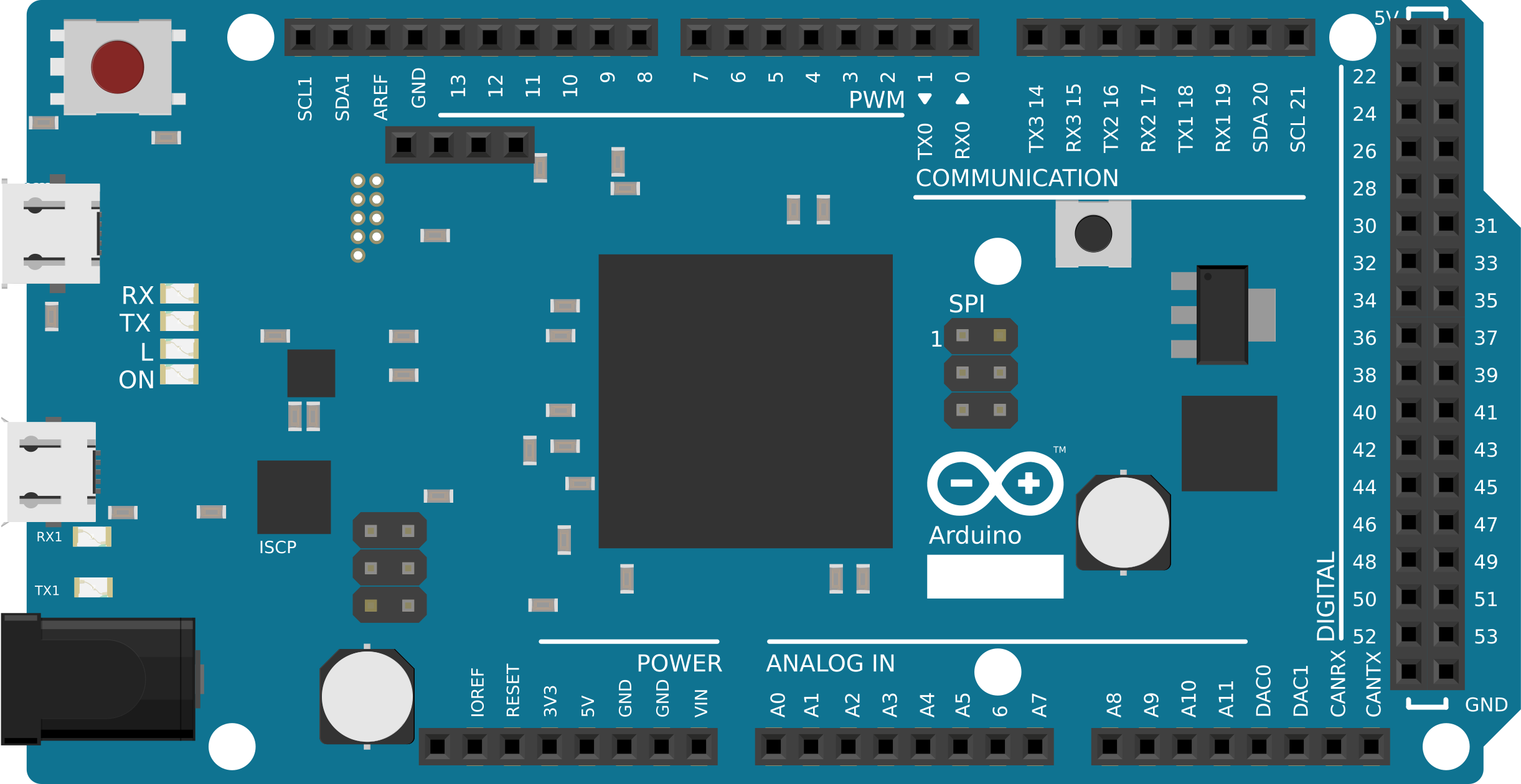
Pin Configuration and Descriptions

Pin Number Function Description
1-54 Digital I/O Digital input/output pins, PWM capable on 12 pins
A0-A11 Analog Input Analog input pins
DAC0, DAC1 Analog Output Digital-to-analog converter outputs
CANRX CAN Bus Receive CAN bus receive pin
CANTX CAN Bus Transmit CAN bus transmit pin
SDA1, SCL1 I2C 1 I2C bus for communication with I2C devices
SDA, SCL I2C 0 Secondary I2C bus
TX0-RX0 UART 0 Serial communication pins
TX1-RX1 UART 1 Additional serial communication pins
TX2-RX2 UART 2 Additional serial communication pins
TX3-RX3 UART 3 Additional serial communication pins
MISO, MOSI, SCK SPI SPI communication pins
SS0-SS3 SPI Slave Select Slave select pins for SPI communication

Usage Instructions

Integrating the Arduino Due into a Circuit

To use the Arduino Due in a circuit:

  1. Powering the Board: Connect a power supply to the board through the barrel jack or the VIN pin. The recommended voltage is between 7V and 12V.
  2. Connecting I/O: Attach sensors, actuators, and other peripherals to the digital and analog pins as required by your project.
  3. Programming the Board: Connect the board to a computer using a micro-USB cable to upload sketches.

Important Considerations and Best Practices

  • Voltage Levels: The Due operates at 3.3V. Applying voltages higher than 3.3V to any I/O pin could damage the board.
  • Maximum Current: Do not draw more than 130 mA from all I/O lines, 800 mA from the 3.3V pin, or 800 mA from the 5V pin.
  • ESD Sensitivity: As with all microcontroller boards, handle the Due with care to avoid electrostatic discharge (ESD) damage.

Example Code for Arduino Due

Here is a simple example of blinking an LED connected to pin 13 on the Arduino Due:

// The setup function runs once when you press reset or power the board
void setup() {
  // initialize digital pin 13 as an output.
  pinMode(13, OUTPUT);
}

// The loop function runs over and over again forever
void loop() {
  digitalWrite(13, HIGH);   // turn the LED on (HIGH is the voltage level)
  delay(1000);              // wait for a second
  digitalWrite(13, LOW);    // turn the LED off by making the voltage LOW
  delay(1000);              // wait for a second
}

Troubleshooting and FAQs

Common Issues

  • Board not recognized: Ensure the micro-USB cable is properly connected and the computer has the necessary drivers installed.
  • Sketch not uploading: Check for correct board and port selection in the Arduino IDE. Also, ensure the bootloader is not corrupted.
  • Unexpected behavior: Verify that all connected components are compatible with 3.3V logic levels.

Solutions and Tips for Troubleshooting

  • Driver Installation: Make sure to install the latest drivers for the Due's Atmel SAM3X8E chip.
  • Power Supply: Use a stable power source to prevent resets during high-current operations.
  • Reset: Press the reset button on the board to restart your program if the Due becomes unresponsive.

FAQs

Q: Can I use 5V sensors with the Due? A: You must use level shifters or voltage dividers to connect 5V sensors to the Due's 3.3V pins.

Q: Is the Due compatible with all Arduino shields? A: Not all shields are compatible due to the Due's 3.3V operating voltage. Check the shield specifications for compatibility.

Q: How can I increase the Due's memory? A: The Due's memory is not expandable. Optimize your code or consider using external storage like an SD card for additional space.