How to Use Adafruit DRV8871: Examples, Pinouts, and Specs
Introduction
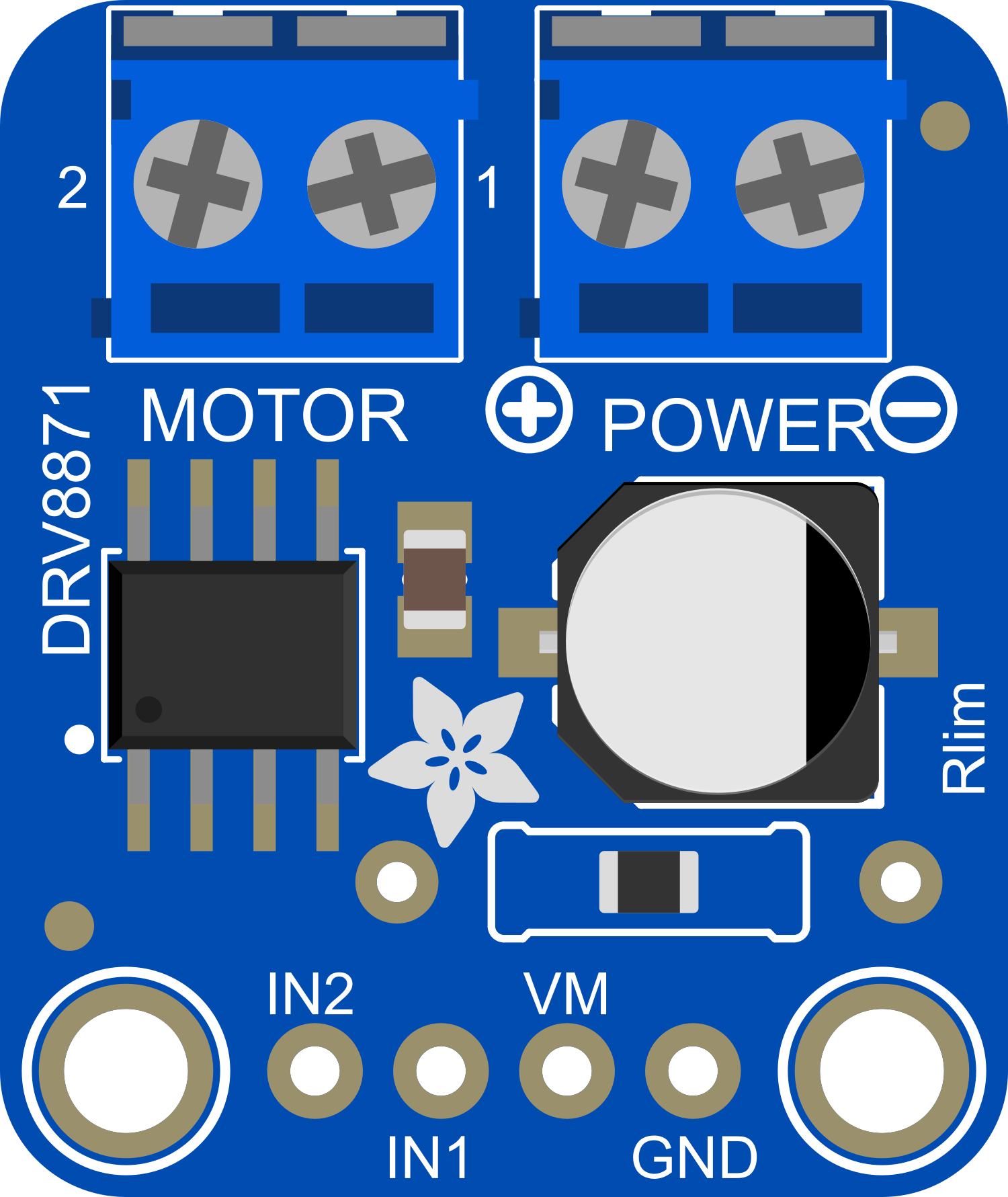
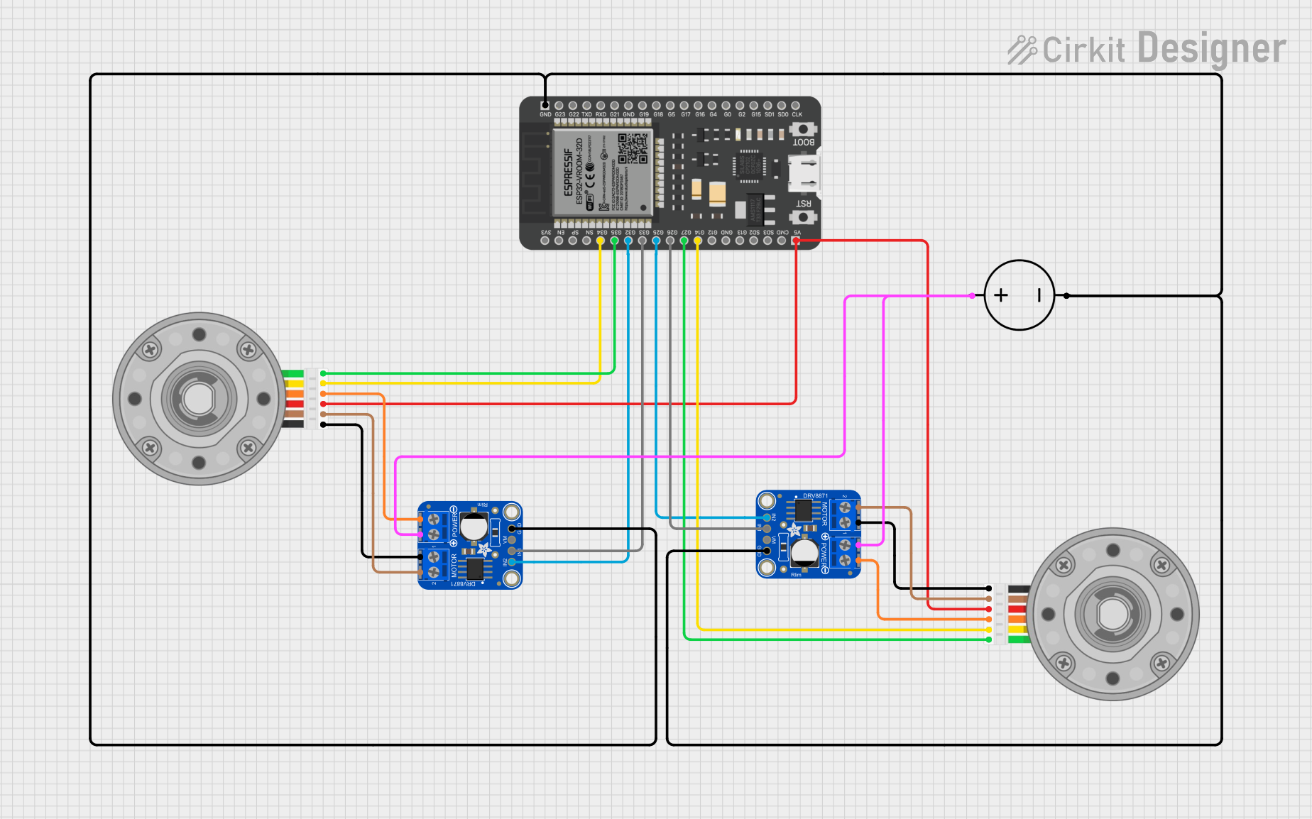
The Adafruit DRV8871 is a robust motor driver board designed to control a single brushed DC motor. It is based on the DRV8871 chip from Texas Instruments, which offers high-efficiency motor driving with advanced protection features. This board is ideal for DIY enthusiasts and professionals looking to drive motors in their projects, such as robotics, automated equipment, and custom vehicles.
Explore Projects Built with Adafruit DRV8871
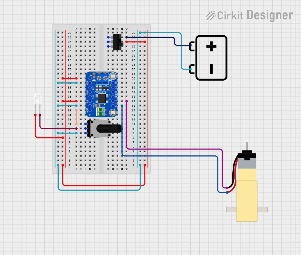
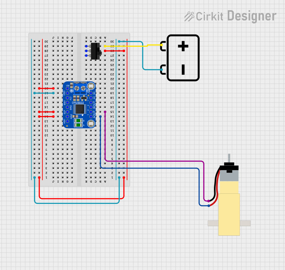
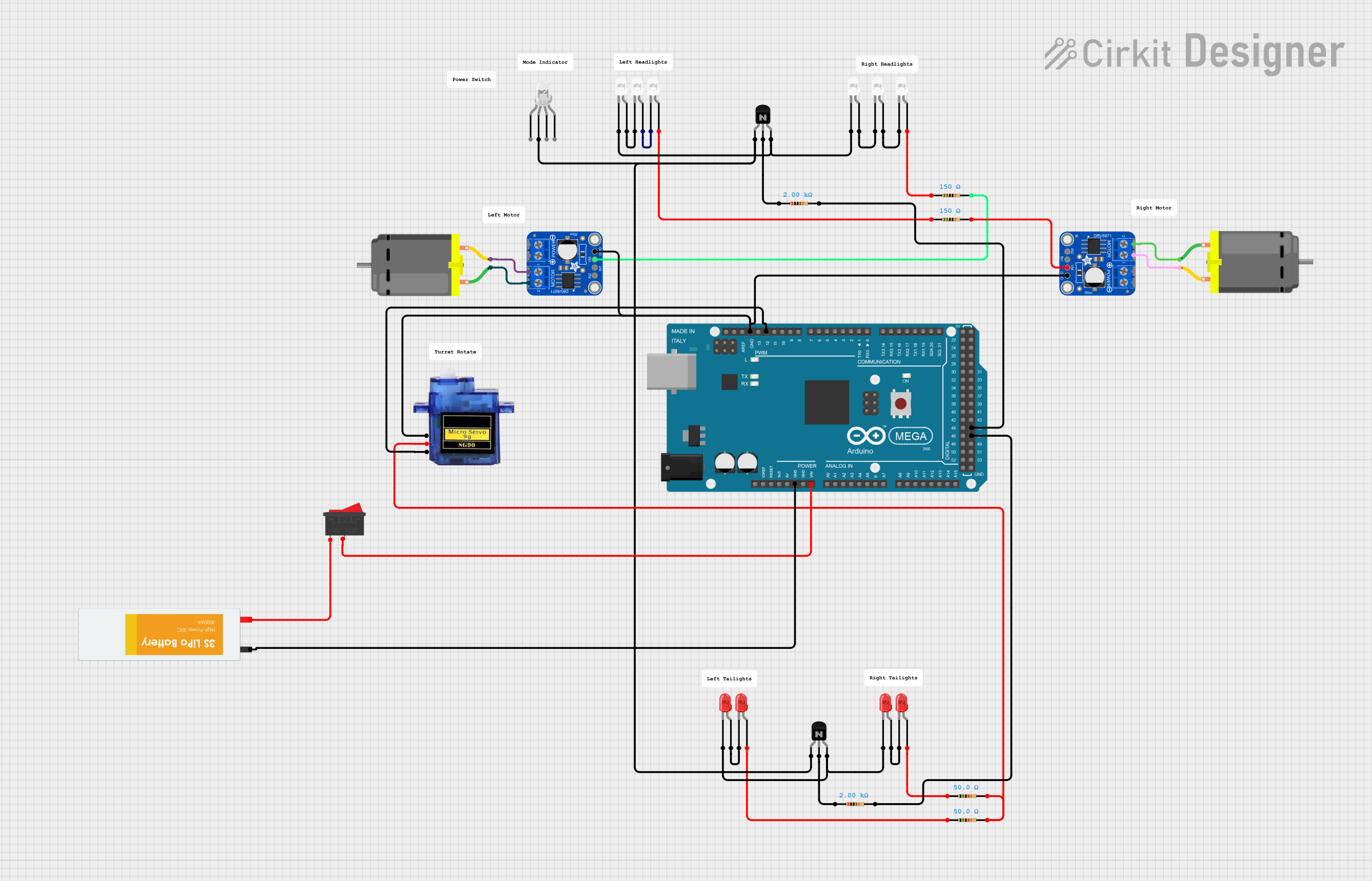
Explore Projects Built with Adafruit DRV8871
Common Applications and Use Cases
- Robotics
- Automated machinery
- Hobbyist projects
- Educational platforms
- Custom vehicles and drones
Technical Specifications
Key Technical Details
- Motor Voltage (VMOT): 6.5 V to 45 V
- Output Current: Up to 3.6 A continuous
- Peak Current: 5.6 A (few milliseconds)
- Logic Voltage (VCC): 2.7 V to 7 V
- PWM Control: Up to 250 kHz
- Protection: Overcurrent, overtemperature, and undervoltage lockout
Pin Configuration and Descriptions
| Pin Number | Name | Description |
|---|---|---|
| 1 | VMOT | Motor power supply (6.5 V to 45 V) |
| 2 | GND | Ground connection |
| 3 | AIN1 | Logic input 1, controls motor direction |
| 4 | AIN2 | Logic input 2, controls motor direction |
| 5 | VCC | Logic power supply (2.7 V to 7 V) |
| 6 | OUT1 | Motor output 1 |
| 7 | OUT2 | Motor output 2 |
| 8 | FAULT | Fault indicator output (open-drain) |
Usage Instructions
How to Use the Component in a Circuit
- Connect the motor to the OUT1 and OUT2 pins.
- Supply the motor voltage (VMOT) to the VMOT pin and connect the ground.
- Provide the logic voltage (VCC) to the VCC pin.
- Use the AIN1 and AIN2 pins to control the motor direction by applying logic high or low signals.
- Optionally, connect the FAULT pin to a microcontroller to monitor for fault conditions.
Important Considerations and Best Practices
- Ensure that the power supply can handle the motor's current requirements.
- Use a flyback diode across the motor terminals to protect against voltage spikes.
- Avoid running the motor at stall current for extended periods to prevent thermal shutdown.
- Implement proper heat dissipation techniques if operating the motor at high currents.
- Always check the wiring and connections to prevent shorts and potential damage.
Example Code for Arduino UNO
// Example code to control a DC motor with the Adafruit DRV8871 and Arduino UNO

const int AIN1 = 2; // Connect to AIN1 on the DRV8871
const int AIN2 = 3; // Connect to AIN2 on the DRV8871

void setup() {
  pinMode(AIN1, OUTPUT);
  pinMode(AIN2, OUTPUT);
}

void loop() {
  // Set motor direction to clockwise
  digitalWrite(AIN1, HIGH);
  digitalWrite(AIN2, LOW);
  delay(1000); // Run motor for 1 second

  // Set motor direction to counterclockwise
  digitalWrite(AIN1, LOW);
  digitalWrite(AIN2, HIGH);
  delay(1000); // Run motor for 1 second

  // Stop the motor
  digitalWrite(AIN1, LOW);
  digitalWrite(AIN2, LOW);
  delay(1000); // Stop motor for 1 second
}
Troubleshooting and FAQs
Common Issues Users Might Face
- Motor not running: Check power supply connections, ensure that VMOT and GND are properly connected, and that the power supply is turned on.
- Overcurrent/Overtemperature shutdown: If the motor draws too much current or the board overheats, it will shut down to protect itself. Check the motor's current draw and ensure adequate cooling.
- Fault indicator active: If the FAULT pin is active, check for short circuits, overcurrent, or overheating conditions.
Solutions and Tips for Troubleshooting
- Verify that all connections are secure and correct.
- Use a multimeter to check for continuity and proper voltages at the pins.
- Ensure that the logic inputs (AIN1 and AIN2) are receiving the correct signals from the microcontroller.
- If the FAULT pin is active, use the microcontroller to read the fault condition and take appropriate action.
FAQs
Q: Can I use the DRV8871 to drive a stepper motor? A: No, the DRV8871 is designed for brushed DC motors, not stepper motors.
Q: What should I do if the motor is drawing too much current? A: Check if the motor is stalled or if there is mechanical resistance. Use a current limiting power supply or add a current sensing resistor to prevent overcurrent conditions.
Q: How can I reverse the motor direction? A: To reverse the motor direction, swap the logic levels on AIN1 and AIN2.
Q: Can I control the speed of the motor with the DRV8871? A: Yes, you can control the speed by applying a PWM signal to one of the AIN pins while keeping the other pin at a logic low level.
Q: Is it necessary to use a heat sink with the DRV8871? A: It depends on the current your motor is drawing. For high current applications, a heat sink is recommended to prevent overheating.
This documentation provides a comprehensive guide to using the Adafruit DRV8871 motor driver board. For further assistance or technical support, please refer to the manufacturer's resources or community forums.