
How to Use DB9 Connector: Examples, Pinouts, and Specs
 Design with DB9 Connector in Cirkit Designer
Introduction
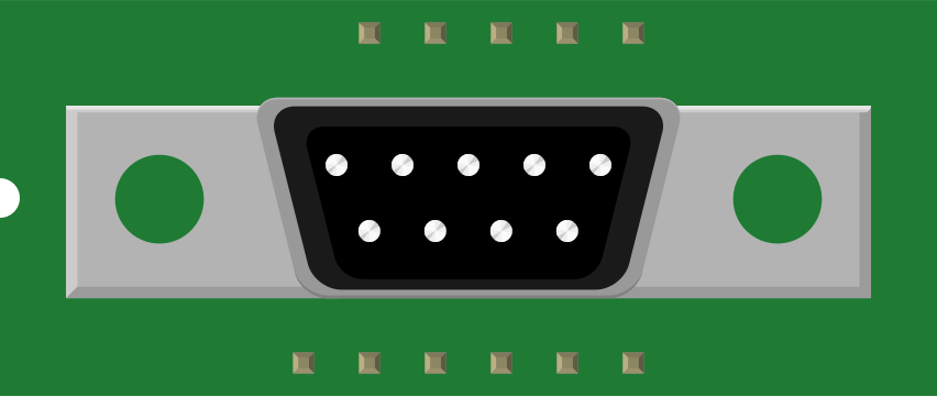
The DB9 connector is a type of electrical connector that features 9 pins arranged in two rows. It is widely used for serial communication, particularly in RS-232 interfaces. This connector is commonly found in computer systems, industrial equipment, and peripheral devices such as modems, printers, and older gaming controllers. Its compact design and reliable performance make it a popular choice for data transmission applications.
Explore Projects Built with DB9 Connector
 Open Project in Cirkit Designer
 Open Project in Cirkit Designer
 Open Project in Cirkit Designer
 Open Project in Cirkit Designer
Explore Projects Built with DB9 Connector
Open Project in Cirkit DesignerOpen Project in Cirkit DesignerOpen Project in Cirkit DesignerOpen Project in Cirkit DesignerCommon Applications:
- Serial communication (RS-232 standard)
- Industrial automation and control systems
- Debugging and programming interfaces
- Legacy computer peripherals (e.g., modems, printers)
- Gaming controllers and joysticks (older systems)
Technical Specifications
Key Technical Details:
- Connector Type: D-subminiature (DB9)
- Number of Pins: 9
- Pin Arrangement: 2 rows (5 pins on the top row, 4 pins on the bottom row)
- Gender: Male (pins) or Female (sockets)
- Voltage Rating: Typically up to 250V
- Current Rating: Typically up to 5A
- Mounting Style: Panel mount or cable mount
- Material: Metal shell with plastic insulator
- Compatibility: RS-232, RS-422, RS-485 standards
Pin Configuration and Descriptions:
The DB9 connector pinout varies depending on the application, but the most common configuration is for RS-232 serial communication. Below is the standard pinout for RS-232:
| Pin Number | Signal Name | Description |
|---|---|---|
| 1 | DCD (Data Carrier Detect) | Indicates the presence of a carrier signal |
| 2 | RXD (Receive Data) | Data received by the device |
| 3 | TXD (Transmit Data) | Data transmitted by the device |
| 4 | DTR (Data Terminal Ready) | Indicates the device is ready to communicate |
| 5 | GND (Ground) | Signal ground |
| 6 | DSR (Data Set Ready) | Indicates the connected device is ready |
| 7 | RTS (Request to Send) | Requests permission to send data |
| 8 | CTS (Clear to Send) | Indicates permission to send data |
| 9 | RI (Ring Indicator) | Indicates an incoming call (modem use) |
Usage Instructions
How to Use the DB9 Connector in a Circuit:
- Identify the Pinout: Refer to the pin configuration table above to understand the function of each pin.
- Connect the Wires: Solder or crimp the wires to the appropriate pins based on your application. Ensure proper insulation to avoid short circuits.
- Mount the Connector: If using a panel-mount DB9 connector, secure it to the panel using screws. For cable-mounted connectors, ensure the strain relief is properly installed.
- Verify Connections: Use a multimeter to check continuity and ensure all connections are correct.
- Connect to Devices: Plug the DB9 connector into the corresponding port on the device. Ensure the male and female connectors are properly aligned.
Important Considerations:
- Signal Levels: Ensure the voltage levels are compatible with the RS-232 standard (typically ±12V).
- Cable Length: For RS-232 communication, keep the cable length under 15 meters to avoid signal degradation.
- Shielding: Use shielded cables to minimize electromagnetic interference (EMI) in noisy environments.
- Gender Matching: Ensure the connector's gender (male or female) matches the port on the device.
Example: Connecting a DB9 Connector to an Arduino UNO
While the Arduino UNO does not have a native DB9 port, you can use a MAX232 IC to convert the RS-232 signal levels to TTL levels compatible with the Arduino. Below is an example of how to interface a DB9 connector with an Arduino UNO:
Circuit Diagram:
- Connect the DB9 pin 2 (RXD) to the MAX232's TX pin.
- Connect the DB9 pin 3 (TXD) to the MAX232's RX pin.
- Connect the MAX232's TTL RX and TX pins to the Arduino's TX (pin 1) and RX (pin 0), respectively.
- Connect the DB9 pin 5 (GND) to the Arduino's GND.
Arduino Code:
// Example code for serial communication with a DB9 connector
void setup() {
  Serial.begin(9600); // Initialize serial communication at 9600 baud
  Serial.println("DB9 Connector Test"); // Send a test message
}

void loop() {
  if (Serial.available() > 0) {
    char receivedChar = Serial.read(); // Read data from the DB9 connector
    Serial.print("Received: ");
    Serial.println(receivedChar); // Echo the received data
  }
}
Troubleshooting and FAQs
Common Issues:
No Communication Between Devices:
- Cause: Incorrect pin connections or mismatched baud rates.
- Solution: Double-check the pinout and ensure the baud rate settings match on both devices.
Signal Interference:
- Cause: Unshielded cables or long cable runs.
- Solution: Use shielded cables and keep cable lengths within the RS-232 standard limits.
Loose Connections:
- Cause: Poor soldering or loose screws in the connector.
- Solution: Inspect and re-solder connections or tighten screws as needed.
Incorrect Gender:
- Cause: Using a male connector instead of a female connector (or vice versa).
- Solution: Use a gender changer or the correct connector type.
FAQs:
Q: Can I use a DB9 connector for RS-485 communication?
- A: Yes, the DB9 connector can be used for RS-485, but the pinout will differ from RS-232. Refer to the specific RS-485 pin configuration.
Q: What is the maximum data rate for RS-232 using a DB9 connector?
- A: The RS-232 standard supports data rates up to 115.2 kbps, but this may vary depending on the cable quality and length.
Q: Can I connect a DB9 connector directly to an Arduino?
- A: No, RS-232 signal levels are not compatible with the Arduino's TTL levels. Use a level shifter like the MAX232 IC to interface the DB9 connector with the Arduino.
By following this documentation, you can effectively use the DB9 connector in your projects and troubleshoot common issues with ease.