How to Use MKE-S01 Ultrasonic Distance Sensor: Examples, Pinouts, and Specs
Introduction
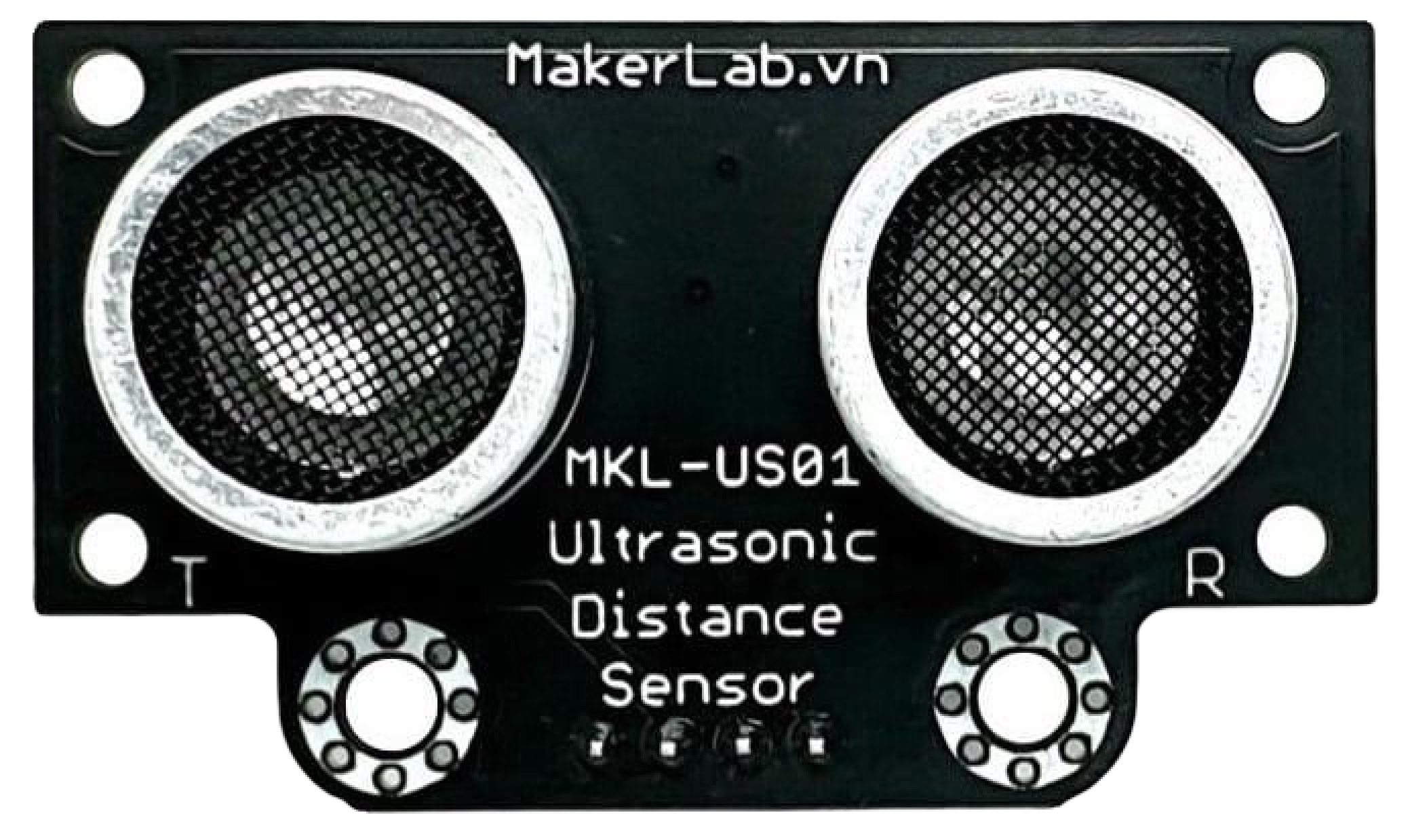
The MKE-S01 Ultrasonic Distance Sensor is an electronic device that measures the distance to an object by emitting ultrasonic waves and calculating the time it takes for the waves to reflect back from the object. This sensor is widely used in robotics, automotive parking sensors, obstacle avoidance systems, and various automation applications due to its non-contact measurement capability and high accuracy.
Explore Projects Built with MKE-S01 Ultrasonic Distance Sensor
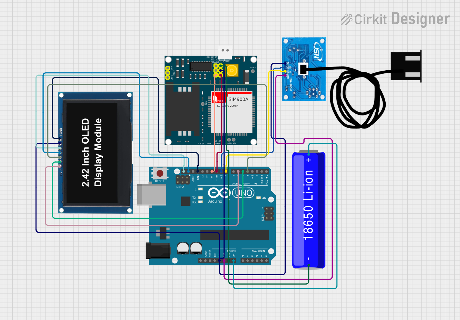
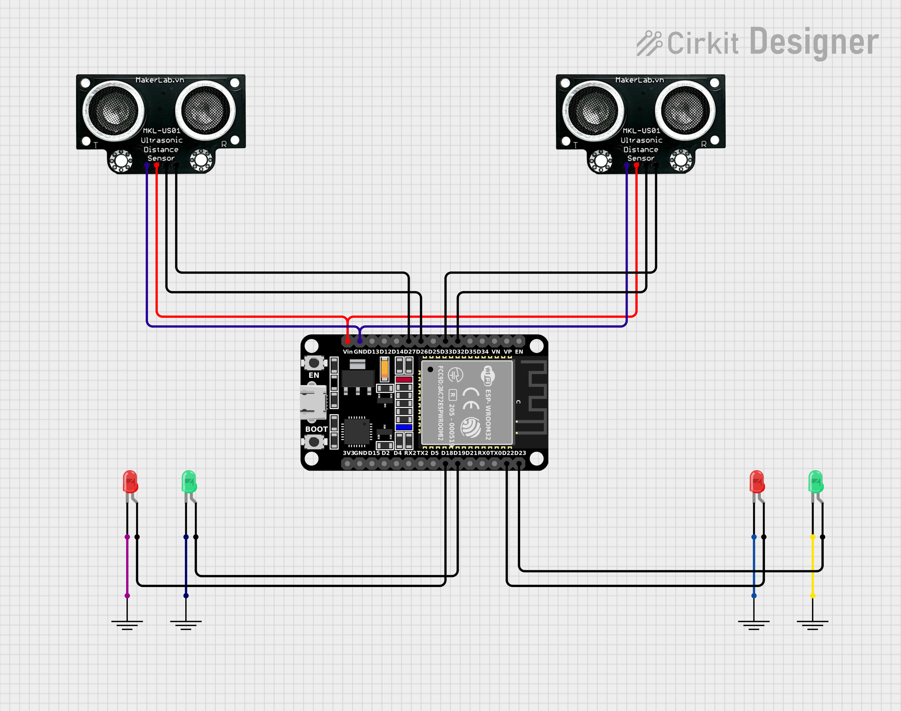
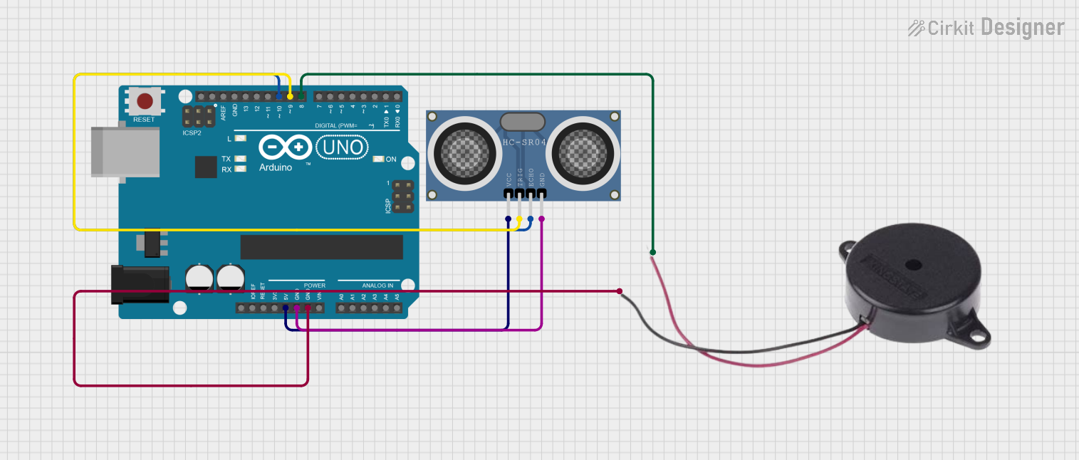
Explore Projects Built with MKE-S01 Ultrasonic Distance Sensor
Technical Specifications
Key Technical Details
- Operating Voltage: 5V DC
- Current Consumption: 15 mA
- Measuring Angle: 15 degrees
- Range: 2 cm to 400 cm
- Resolution: 0.3 cm
- Operating Temperature: -20°C to +70°C
Pin Configuration and Descriptions
| Pin Number | Pin Name | Description |
|---|---|---|
| 1 | VCC | Power supply (5V DC) |
| 2 | Trig | Trigger input (TTL pulse) |
| 3 | Echo | Echo output (TTL level signal) |
| 4 | GND | Ground |
Usage Instructions
How to Use the Component in a Circuit
- Power Supply: Connect the VCC pin to a 5V power supply and the GND pin to the ground.
- Triggering: Send a 10 µs TTL pulse to the Trig pin to initiate the measurement.
- Receiving Echo: Monitor the Echo pin; the duration of the high-level signal will indicate the time taken for the sound wave to return.
- Calculating Distance: Calculate the distance by using the speed of sound and the time interval between sending and receiving the pulse.
Important Considerations and Best Practices
- Ensure that the sensor is mounted on a stable platform to avoid erroneous readings due to vibrations.
- Avoid placing objects within the minimum measurable range (2 cm) as this may cause inaccurate measurements.
- Keep the sensor away from acoustic noise sources and ensure a clear path between the sensor and the target object.
- Use a pull-up resistor if the Echo signal is weak or unreliable.
Example Code for Arduino UNO
// Define sensor pins
const int trigPin = 9;
const int echoPin = 10;

void setup() {
  // Initialize serial communication
  Serial.begin(9600);
  // Define pin modes
  pinMode(trigPin, OUTPUT);
  pinMode(echoPin, INPUT);
}

void loop() {
  // Clear the trigPin by setting it LOW
  digitalWrite(trigPin, LOW);
  delayMicroseconds(2);

  // Set the trigPin HIGH for 10 microseconds to send the ultrasonic pulse
  digitalWrite(trigPin, HIGH);
  delayMicroseconds(10);
  digitalWrite(trigPin, LOW);

  // Read the echoPin; pulseIn returns the duration in microseconds
  long duration = pulseIn(echoPin, HIGH);

  // Calculate the distance (in cm) based on the speed of sound (34300 cm/s)
  long distance = duration * 0.0343 / 2;

  // Print the distance to the Serial Monitor
  Serial.print("Distance: ");
  Serial.print(distance);
  Serial.println(" cm");

  // Delay between measurements
  delay(1000);
}
Troubleshooting and FAQs
Common Issues
- Inaccurate Readings: Ensure that the sensor is not facing any obstacles within 2 cm and that the path to the target is clear.
- No Readings: Check the power supply and wiring connections. Ensure that the Trig pin is receiving the 10 µs pulse.
- Intermittent Readings: This could be due to electrical noise. Use a pull-up resistor on the Echo pin and ensure proper grounding.
Solutions and Tips for Troubleshooting
- If the sensor is not functioning, first check the power supply and ensure that the VCC and GND pins are correctly connected.
- Verify that the Trig and Echo pins are connected to the correct pins on the Arduino.
- Use the
Serial.printfunction to debug and monitor the duration and distance values. - For continuous operation, include a delay between measurements to prevent signal interference.
FAQs
Q: Can the sensor measure distances beyond 400 cm? A: The sensor is designed to measure up to 400 cm. Measurements beyond this range may be unreliable.
Q: Is the sensor waterproof? A: The MKE-S01 is not typically waterproof. Special care should be taken to avoid exposure to moisture.
Q: How can I increase the measurement angle of the sensor? A: The measurement angle is fixed due to the design of the sensor. To cover a wider area, use multiple sensors or mechanically rotate the sensor.
Q: Can the sensor be used with a 3.3V system? A: The sensor is rated for 5V operation. Using it with a 3.3V system may result in improper functioning. Use a level shifter if necessary.