
How to Use 74HC161: Examples, Pinouts, and Specs
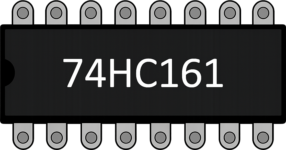
 Design with 74HC161 in Cirkit Designer
Introduction
The 74HC161 is a high-speed, synchronous 4-bit binary counter with parallel load capability. It is widely used in digital circuits for counting applications, offering a simple and efficient way to implement counting functions. The counter can operate in both up and down counting modes and is designed to work with a wide range of supply voltages, making it suitable for various applications.
Explore Projects Built with 74HC161
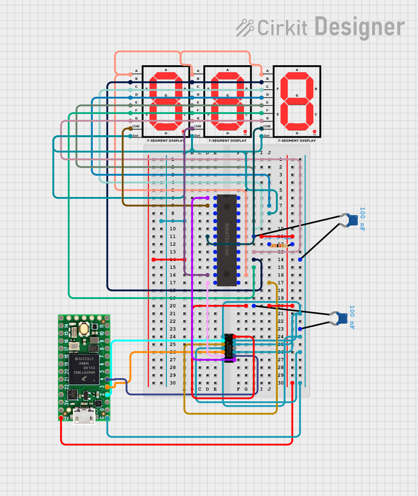 Open Project in Cirkit Designer
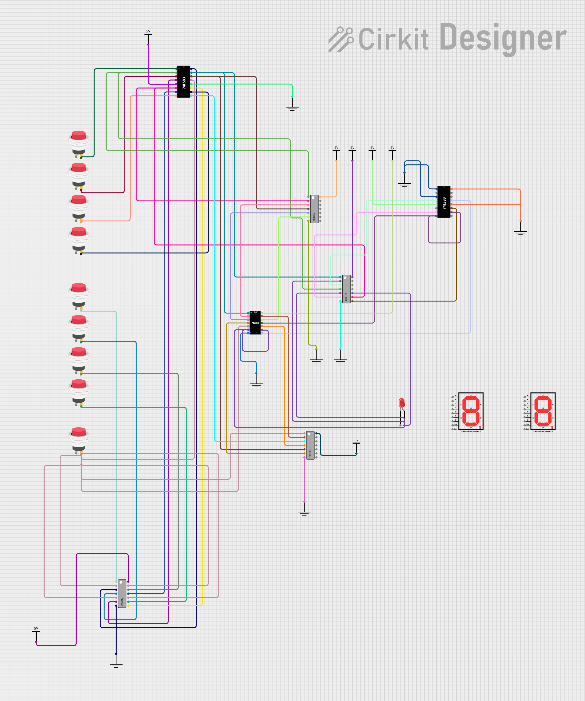 Open Project in Cirkit Designer
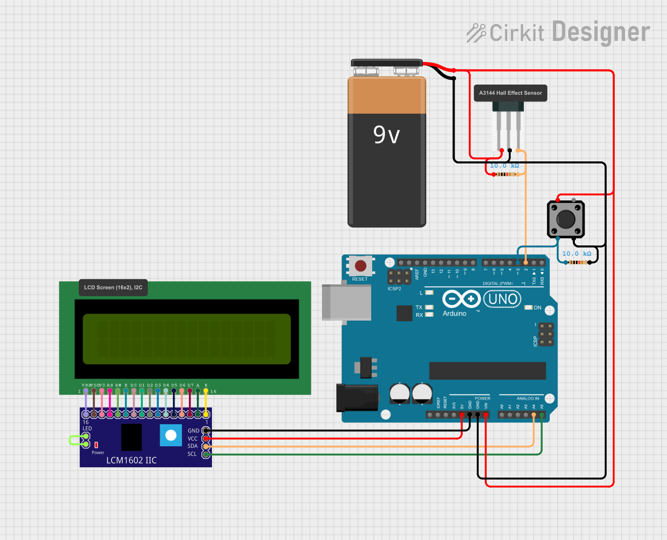 Open Project in Cirkit Designer
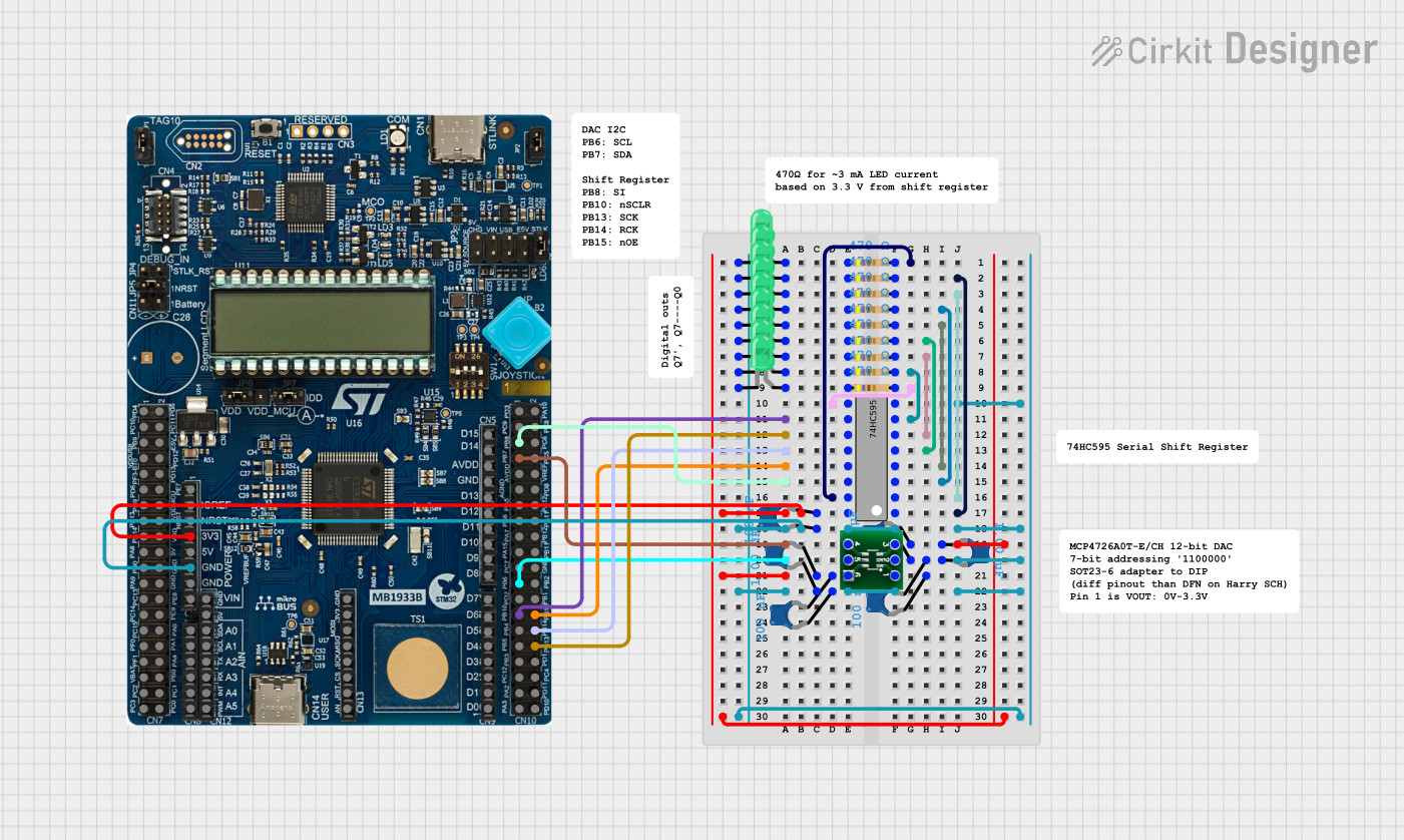 Open Project in Cirkit Designer
Explore Projects Built with 74HC161
Open Project in Cirkit DesignerOpen Project in Cirkit DesignerOpen Project in Cirkit DesignerOpen Project in Cirkit DesignerCommon Applications
- Digital clocks and timers
- Frequency dividers
- Event counters
- Sequential logic circuits
- Microcontroller-based systems
Technical Specifications
Key Technical Details
- Supply Voltage (Vcc): 2V to 6V
- Input High Voltage (VIH): 2.0V (min) at 4.5V Vcc
- Input Low Voltage (VIL): 0.8V (max) at 4.5V Vcc
- Maximum Clock Frequency: 50 MHz (typical at 5V)
- Propagation Delay (Clock to Output): 15 ns (typical at 5V)
- Operating Temperature Range: -40°C to +125°C
- Output Drive Current: ±6 mA at 5V
Pin Configuration and Descriptions
The 74HC161 is a 16-pin IC with the following pinout:
| Pin No. | Pin Name | Description |
|---|---|---|
| 1 | MR | Master Reset (Active Low) - Resets the counter to 0 |
| 2 | CP | Clock Input - Rising edge triggers the counter |
| 3 | CET | Count Enable (Active High) - Enables counting |
| 4 | CEP | Count Enable Parallel (Active High) - Enables counting |
| 5 | D0 | Parallel Data Input (Least Significant Bit) |
| 6 | D1 | Parallel Data Input |
| 7 | D2 | Parallel Data Input |
| 8 | GND | Ground - Connect to circuit ground |
| 9 | D3 | Parallel Data Input (Most Significant Bit) |
| 10 | Q3 | Output (Most Significant Bit) |
| 11 | Q2 | Output |
| 12 | Q1 | Output |
| 13 | Q0 | Output (Least Significant Bit) |
| 14 | TC | Terminal Count Output - Indicates when the counter reaches its maximum |
| 15 | PL | Parallel Load (Active Low) - Loads data from D0-D3 into the counter |
| 16 | Vcc | Supply Voltage - Connect to positive power supply |
Usage Instructions
How to Use the 74HC161 in a Circuit
- Power Supply: Connect the Vcc pin to a power supply (2V to 6V) and the GND pin to ground.
- Clock Input: Provide a clock signal to the CP pin. The counter increments or decrements on the rising edge of the clock.
- Enable Counting: Ensure both CET and CEP are high to enable counting. If either is low, the counter will not increment.
- Resetting the Counter: To reset the counter to 0, pull the MR pin low momentarily.
- Parallel Loading: To load a specific value into the counter, set the desired binary value on D0-D3, then pull the PL pin low momentarily.
- Reading Outputs: The current count value is available on Q0-Q3, with Q0 being the least significant bit and Q3 the most significant bit.
Important Considerations
- Use decoupling capacitors (e.g., 0.1 µF) near the Vcc pin to stabilize the power supply.
- Avoid floating inputs by connecting unused inputs to Vcc or GND.
- Ensure the clock signal is clean and free of noise to prevent erratic counting behavior.
Example: Connecting the 74HC161 to an Arduino UNO
The 74HC161 can be interfaced with an Arduino UNO to create a simple counter. Below is an example code to increment the counter and read its output:
// Define pin connections
const int clockPin = 2;  // Arduino pin connected to CP (Clock Input)
const int resetPin = 3;  // Arduino pin connected to MR (Master Reset)
const int enablePin = 4; // Arduino pin connected to CET and CEP
const int plPin = 5;     // Arduino pin connected to PL (Parallel Load)

// Define output pins for Q0-Q3
const int q0Pin = 6;     // Q0 (LSB)
const int q1Pin = 7;     // Q1
const int q2Pin = 8;     // Q2
const int q3Pin = 9;     // Q3

void setup() {
  // Set control pins as outputs
  pinMode(clockPin, OUTPUT);
  pinMode(resetPin, OUTPUT);
  pinMode(enablePin, OUTPUT);
  pinMode(plPin, OUTPUT);

  // Set output pins as inputs
  pinMode(q0Pin, INPUT);
  pinMode(q1Pin, INPUT);
  pinMode(q2Pin, INPUT);
  pinMode(q3Pin, INPUT);

  // Initialize control pins
  digitalWrite(resetPin, HIGH); // Keep reset inactive
  digitalWrite(enablePin, HIGH); // Enable counting
  digitalWrite(plPin, HIGH);     // Keep parallel load inactive
}

void loop() {
  // Generate a clock pulse
  digitalWrite(clockPin, HIGH);
  delay(10); // Short delay for clock pulse
  digitalWrite(clockPin, LOW);
  delay(10);

  // Read and print the counter value
  int count = digitalRead(q0Pin) |
              (digitalRead(q1Pin) << 1) |
              (digitalRead(q2Pin) << 2) |
              (digitalRead(q3Pin) << 3);

  Serial.begin(9600);
  Serial.print("Counter Value: ");
  Serial.println(count);

  delay(500); // Wait before the next clock pulse
}
Notes:
- Ensure proper pull-up or pull-down resistors are used if needed.
- The clock signal should not exceed the maximum frequency specified in the datasheet.
Troubleshooting and FAQs
Common Issues
Counter Not Incrementing:
- Ensure both CET and CEP are high.
- Verify the clock signal is reaching the CP pin.
- Check for proper power supply connections.
Incorrect Output Values:
- Verify the connections to Q0-Q3.
- Ensure the clock signal is clean and free of noise.
- Check if the counter is being reset unintentionally.
Parallel Load Not Working:
- Ensure the PL pin is momentarily pulled low to load the data.
- Verify the binary value on D0-D3 is correctly set.
Tips for Troubleshooting
- Use an oscilloscope to verify the clock signal and other control signals.
- Double-check all connections against the pinout table.
- Test the IC in a simple circuit before integrating it into a larger system.
FAQs
Q: Can the 74HC161 count down?
A: No, the 74HC161 is designed for up-counting only. For down-counting, consider using a different counter IC or additional logic.
Q: What happens if the clock frequency is too high?
A: The counter may fail to operate correctly due to propagation delays. Ensure the clock frequency is within the specified range.
Q: Can I cascade multiple 74HC161 ICs?
A: Yes, the TC (Terminal Count) output can be used to cascade multiple counters for higher bit-width counting.