How to Use BFD-1000 5 CHANNEL INFRARED: Examples, Pinouts, and Specs
Introduction
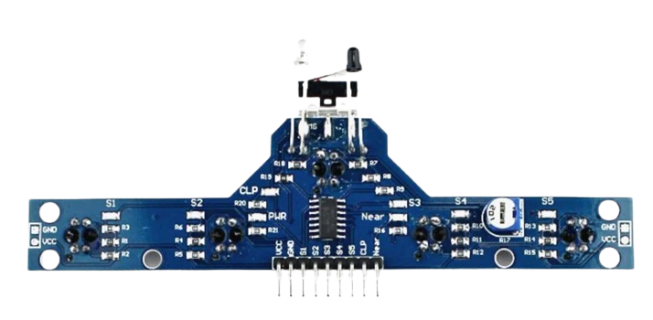
The BFD-1000 is a versatile 5-channel infrared sensor module designed by Arduino, part ID: UNO. This sensor module is primarily used for detecting infrared light, making it an excellent choice for applications such as line-following robots, obstacle detection, and other automation projects. The module's five infrared sensors allow for precise detection and tracking of lines or objects, providing reliable performance in various environments.
Explore Projects Built with BFD-1000 5 CHANNEL INFRARED
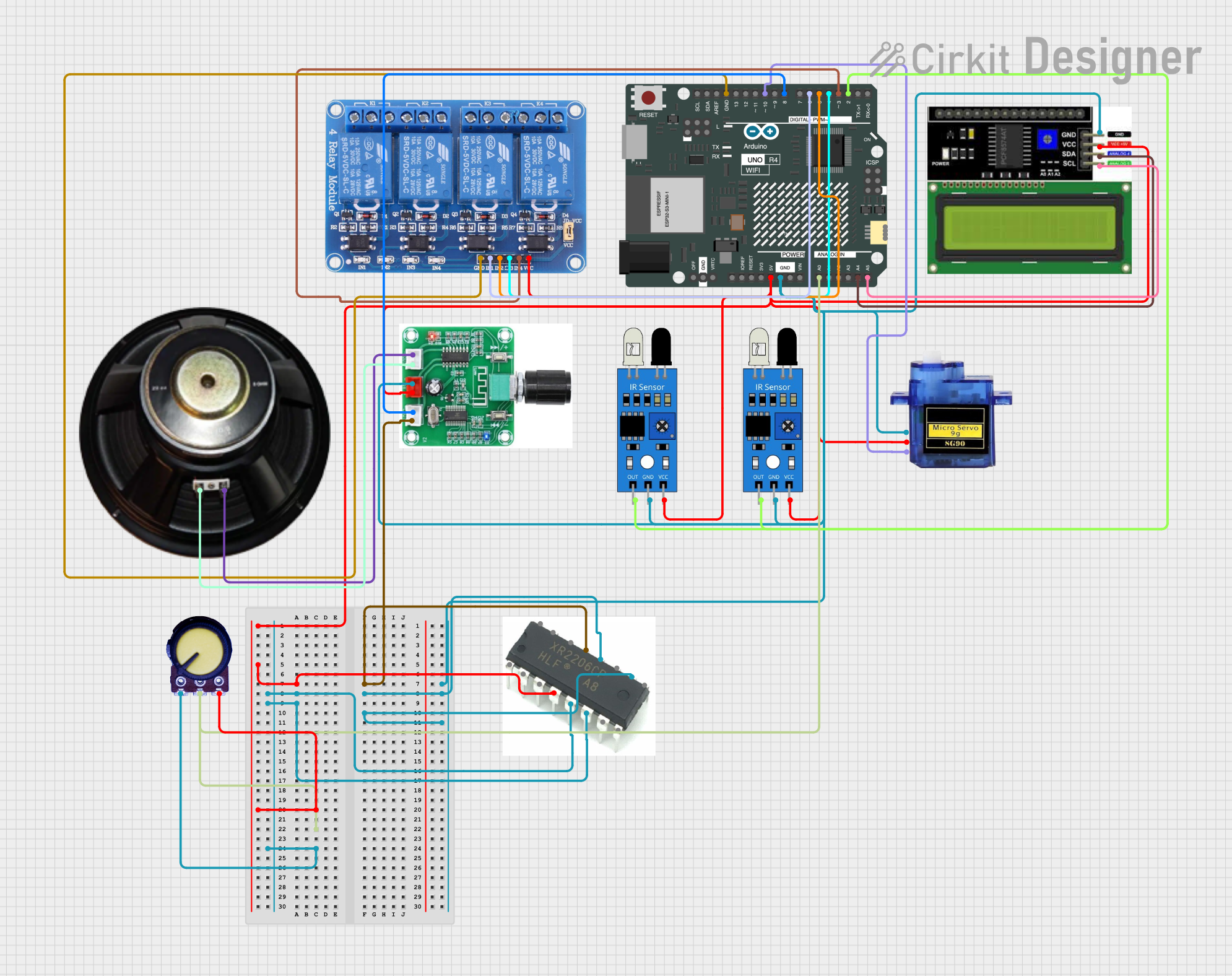

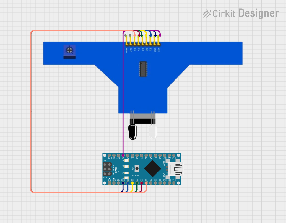

Explore Projects Built with BFD-1000 5 CHANNEL INFRARED
Technical Specifications
Key Technical Details
| Parameter | Value |
|---|---|
| Operating Voltage | 3.3V - 5V |
| Current Consumption | 20mA (typical) |
| Output Type | Digital |
| Detection Range | 1mm - 60mm |
| Dimensions | 70mm x 20mm x 10mm |
| Weight | 10g |
Pin Configuration and Descriptions
| Pin Number | Pin Name | Description |
|---|---|---|
| 1 | VCC | Power supply (3.3V - 5V) |
| 2 | GND | Ground |
| 3 | OUT1 | Digital output from sensor 1 |
| 4 | OUT2 | Digital output from sensor 2 |
| 5 | OUT3 | Digital output from sensor 3 |
| 6 | OUT4 | Digital output from sensor 4 |
| 7 | OUT5 | Digital output from sensor 5 |
Usage Instructions
How to Use the Component in a Circuit
- Power Supply: Connect the VCC pin to a 3.3V or 5V power supply and the GND pin to the ground of your circuit.
- Digital Outputs: Connect the OUT1 to OUT5 pins to the digital input pins of your microcontroller (e.g., Arduino UNO).
- Placement: Position the sensor module so that the infrared sensors face the surface or objects you want to detect.
Example Circuit Diagram
Arduino UNO          BFD-1000
-----------          --------
5V        ----------> VCC
GND       ----------> GND
D2        ----------> OUT1
D3        ----------> OUT2
D4        ----------> OUT3
D5        ----------> OUT4
D6        ----------> OUT5
Important Considerations and Best Practices
- Power Supply: Ensure that the power supply voltage is within the specified range (3.3V - 5V) to avoid damaging the sensor.
- Distance: The detection range is between 1mm and 60mm. Ensure that the objects or lines to be detected are within this range for optimal performance.
- Interference: Avoid placing the sensor module in direct sunlight or near other strong infrared sources, as this may interfere with its operation.
Sample Arduino Code
// BFD-1000 5 Channel Infrared Sensor Module Example Code
// This code reads the digital outputs from the BFD-1000 and prints the
// values to the Serial Monitor.

const int sensorPins[5] = {2, 3, 4, 5, 6}; // Define sensor pins

void setup() {
  Serial.begin(9600); // Initialize serial communication
  for (int i = 0; i < 5; i++) {
    pinMode(sensorPins[i], INPUT); // Set sensor pins as input
  }
}

void loop() {
  for (int i = 0; i < 5; i++) {
    int sensorValue = digitalRead(sensorPins[i]); // Read sensor value
    Serial.print("Sensor ");
    Serial.print(i + 1);
    Serial.print(": ");
    Serial.println(sensorValue); // Print sensor value
  }
  delay(500); // Wait for 500 milliseconds
}
Troubleshooting and FAQs
Common Issues Users Might Face
No Output from Sensors:
- Solution: Check the power supply connections to ensure the module is receiving the correct voltage. Verify that the ground connection is secure.
Inconsistent Readings:
- Solution: Ensure that the sensor module is positioned correctly and that the surface or objects to be detected are within the specified detection range. Avoid interference from other infrared sources.
All Sensors Reading High or Low:
- Solution: Verify that the sensor module is not exposed to direct sunlight or other strong infrared sources. Check for any obstructions or dirt on the sensor lenses.
FAQs
Q1: Can the BFD-1000 detect colors?
- A1: No, the BFD-1000 is designed to detect infrared light and is primarily used for detecting lines or objects based on their infrared reflectivity.
Q2: What is the maximum detection range of the BFD-1000?
- A2: The maximum detection range is approximately 60mm.
Q3: Can I use the BFD-1000 with a 3.3V microcontroller?
- A3: Yes, the BFD-1000 can operate with a power supply voltage of 3.3V to 5V, making it compatible with 3.3V microcontrollers.
Q4: How do I clean the sensor lenses?
- A4: Use a soft, dry cloth to gently clean the sensor lenses. Avoid using any liquids or abrasive materials.
By following this documentation, users can effectively integrate the BFD-1000 5 Channel Infrared Sensor Module into their projects, ensuring reliable performance and accurate detection.