Cirkit Designer Logo
Cirkit Designer
Your all-in-one circuit design IDE
Home / 
Component Documentation

How to Use ESP32-S3 WROOM N16R8 FREENOVE: Examples, Pinouts, and Specs

Image of ESP32-S3 WROOM N16R8 FREENOVE
Cirkit Designer LogoDesign with ESP32-S3 WROOM N16R8 FREENOVE in Cirkit Designer

Introduction

The ESP32-S3 WROOM N16R8 FREENOVE is a powerful microcontroller module designed for Internet of Things (IoT) applications. Manufactured by FREENOVE, this module features dual-core processing, integrated Wi-Fi and Bluetooth 5.0 capabilities, and 16MB of flash memory. It is ideal for projects requiring high performance, low power consumption, and robust wireless connectivity. The ESP32-S3 WROOM N16R8 also supports a wide range of peripherals, making it versatile for various applications.

Explore Projects Built with ESP32-S3 WROOM N16R8 FREENOVE

Use Cirkit Designer to design, explore, and prototype these projects online. Some projects support real-time simulation. Click "Open Project" to start designing instantly!
ESP32-Based GPS Tracker with SD Card Logging and Barometric Sensor
Image of gps projekt circuit: A project utilizing ESP32-S3 WROOM N16R8 FREENOVE in a practical application
This circuit features an ESP32 Wroom Dev Kit as the main microcontroller, interfaced with an MPL3115A2 sensor for pressure and temperature readings, and a Neo 6M GPS module for location tracking. The ESP32 is also connected to an SD card reader for data logging purposes. A voltage regulator is used to step down the USB power supply to 3.3V, which powers the ESP32, the sensor, and the SD card reader.
Cirkit Designer LogoOpen Project in Cirkit Designer
ESP32-Based Multi-Sensor Health Monitoring System with Bluetooth Connectivity
Image of circuit diagram: A project utilizing ESP32-S3 WROOM N16R8 FREENOVE in a practical application
This circuit features an ESP32-WROOM-32UE microcontroller as the central processing unit, interfacing with a variety of sensors and modules. It includes a MAX30100 pulse oximeter and heart-rate sensor, an MLX90614 infrared thermometer, an HC-05 Bluetooth module for wireless communication, and a Neo 6M GPS module for location tracking. All components are powered by a common voltage supply and are connected to specific GPIO pins on the ESP32 for data exchange, with the sensors using I2C communication and the modules using UART.
Cirkit Designer LogoOpen Project in Cirkit Designer
ESP32-Based Vibration Motor Controller with I2C IO Expansion
Image of VIBRATYION: A project utilizing ESP32-S3 WROOM N16R8 FREENOVE in a practical application
This circuit features an ESP32 Wroom Dev Kit microcontroller interfaced with an MCP23017 I/O expansion board via I2C communication, utilizing GPIO 21 and GPIO 22 for SDA and SCL lines, respectively. A vibration motor is controlled by an NPN transistor acting as a switch, with a diode for back EMF protection and a resistor to limit base current. The ESP32 can control the motor by sending signals to the MCP23017, which then interfaces with the transistor to turn the motor on or off.
Cirkit Designer LogoOpen Project in Cirkit Designer
ESP32-WROOM-32UE Wi-Fi Controlled Robotic Car with OLED Display and RGB LED
Image of mkrl bot: A project utilizing ESP32-S3 WROOM N16R8 FREENOVE in a practical application
This circuit is a WiFi-controlled robotic system powered by an ESP32 microcontroller. It features an OLED display for status messages, an RGB LED for visual feedback, and dual hobby gearmotors driven by an L9110 motor driver for movement. The system is powered by a 4 x AAA battery pack regulated to 5V using a 7805 voltage regulator.
Cirkit Designer LogoOpen Project in Cirkit Designer

Explore Projects Built with ESP32-S3 WROOM N16R8 FREENOVE

Use Cirkit Designer to design, explore, and prototype these projects online. Some projects support real-time simulation. Click "Open Project" to start designing instantly!
Image of gps projekt circuit: A project utilizing ESP32-S3 WROOM N16R8 FREENOVE in a practical application
ESP32-Based GPS Tracker with SD Card Logging and Barometric Sensor
This circuit features an ESP32 Wroom Dev Kit as the main microcontroller, interfaced with an MPL3115A2 sensor for pressure and temperature readings, and a Neo 6M GPS module for location tracking. The ESP32 is also connected to an SD card reader for data logging purposes. A voltage regulator is used to step down the USB power supply to 3.3V, which powers the ESP32, the sensor, and the SD card reader.
Cirkit Designer LogoOpen Project in Cirkit Designer
Image of circuit diagram: A project utilizing ESP32-S3 WROOM N16R8 FREENOVE in a practical application
ESP32-Based Multi-Sensor Health Monitoring System with Bluetooth Connectivity
This circuit features an ESP32-WROOM-32UE microcontroller as the central processing unit, interfacing with a variety of sensors and modules. It includes a MAX30100 pulse oximeter and heart-rate sensor, an MLX90614 infrared thermometer, an HC-05 Bluetooth module for wireless communication, and a Neo 6M GPS module for location tracking. All components are powered by a common voltage supply and are connected to specific GPIO pins on the ESP32 for data exchange, with the sensors using I2C communication and the modules using UART.
Cirkit Designer LogoOpen Project in Cirkit Designer
Image of VIBRATYION: A project utilizing ESP32-S3 WROOM N16R8 FREENOVE in a practical application
ESP32-Based Vibration Motor Controller with I2C IO Expansion
This circuit features an ESP32 Wroom Dev Kit microcontroller interfaced with an MCP23017 I/O expansion board via I2C communication, utilizing GPIO 21 and GPIO 22 for SDA and SCL lines, respectively. A vibration motor is controlled by an NPN transistor acting as a switch, with a diode for back EMF protection and a resistor to limit base current. The ESP32 can control the motor by sending signals to the MCP23017, which then interfaces with the transistor to turn the motor on or off.
Cirkit Designer LogoOpen Project in Cirkit Designer
Image of mkrl bot: A project utilizing ESP32-S3 WROOM N16R8 FREENOVE in a practical application
ESP32-WROOM-32UE Wi-Fi Controlled Robotic Car with OLED Display and RGB LED
This circuit is a WiFi-controlled robotic system powered by an ESP32 microcontroller. It features an OLED display for status messages, an RGB LED for visual feedback, and dual hobby gearmotors driven by an L9110 motor driver for movement. The system is powered by a 4 x AAA battery pack regulated to 5V using a 7805 voltage regulator.
Cirkit Designer LogoOpen Project in Cirkit Designer

Common Applications and Use Cases

  • Smart home devices (e.g., smart lights, thermostats)
  • Wearable technology
  • Industrial IoT systems
  • Wireless sensor networks
  • Robotics and automation
  • Edge computing and AI/ML applications

Technical Specifications

The ESP32-S3 WROOM N16R8 is packed with features that make it suitable for demanding IoT projects. Below are its key technical specifications:

General Specifications

Parameter Value
Microcontroller ESP32-S3
Flash Memory 16MB
RAM 8MB
Wireless Connectivity Wi-Fi 802.11 b/g/n, Bluetooth 5.0
Operating Voltage 3.3V
Operating Temperature -40°C to 85°C
Dimensions 18mm x 25.5mm x 3mm

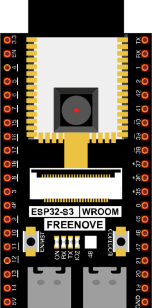
Pin Configuration and Descriptions

The ESP32-S3 WROOM N16R8 module has multiple GPIO pins and interfaces. Below is a summary of the pin configuration:

Pin Number Pin Name Description
1 GND Ground
2 3V3 3.3V Power Supply
3 EN Enable pin (active high)
4 IO0 GPIO0, used for boot mode selection
5 IO1 GPIO1, general-purpose I/O
6 IO2 GPIO2, general-purpose I/O
7 IO3 GPIO3, general-purpose I/O
8 RXD UART Receive
9 TXD UART Transmit
10 IO4 GPIO4, general-purpose I/O
11 IO5 GPIO5, general-purpose I/O
12 IO6 GPIO6, general-purpose I/O
13 IO7 GPIO7, general-purpose I/O
14 IO8 GPIO8, general-purpose I/O
15 IO9 GPIO9, general-purpose I/O

Note: The ESP32-S3 WROOM N16R8 supports additional pins and interfaces, such as SPI, I2C, and ADC. Refer to the full datasheet for a complete pinout.

Usage Instructions

How to Use the ESP32-S3 WROOM N16R8 in a Circuit

  1. Power Supply: Connect the 3V3 pin to a 3.3V power source and GND to ground.
  2. Boot Mode: To upload code, connect GPIO0 to GND during reset to enter bootloader mode.
  3. Peripherals: Use the GPIO pins to connect sensors, actuators, or other peripherals. Ensure the voltage levels are compatible.
  4. Programming: The module can be programmed using the Arduino IDE, PlatformIO, or ESP-IDF.

Example: Connecting to an Arduino UNO

The ESP32-S3 WROOM N16R8 can communicate with an Arduino UNO via UART. Below is an example of how to send data from the Arduino to the ESP32-S3.

Arduino Code

// Example: Sending data from Arduino UNO to ESP32-S3 via UART
void setup() {
  Serial.begin(9600); // Initialize serial communication at 9600 baud
}

void loop() {
  Serial.println("Hello from Arduino!"); // Send data to ESP32-S3
  delay(1000); // Wait for 1 second
}

ESP32-S3 Code

// Example: Receiving data on ESP32-S3 from Arduino UNO
void setup() {
  Serial.begin(9600); // Initialize serial communication at 9600 baud
}

void loop() {
  if (Serial.available()) { // Check if data is available
    String data = Serial.readString(); // Read the incoming data
    Serial.println("Received: " + data); // Print the received data
  }
}

Important Considerations and Best Practices

  • Power Supply: Ensure a stable 3.3V power source to avoid damage to the module.
  • GPIO Voltage Levels: The GPIO pins are not 5V tolerant. Use level shifters if interfacing with 5V devices.
  • Antenna Placement: For optimal Wi-Fi and Bluetooth performance, avoid placing the module near metal objects or inside enclosures that block RF signals.
  • Firmware Updates: Keep the firmware updated to benefit from the latest features and security patches.

Troubleshooting and FAQs

Common Issues and Solutions

  1. Module Not Responding

    • Cause: Incorrect power supply or wiring.
    • Solution: Verify the power supply is 3.3V and check all connections.
  2. Cannot Upload Code

    • Cause: GPIO0 not connected to GND during reset.
    • Solution: Ensure GPIO0 is grounded when resetting the module to enter bootloader mode.
  3. Wi-Fi Connection Fails

    • Cause: Incorrect SSID or password.
    • Solution: Double-check the Wi-Fi credentials in your code.
  4. Bluetooth Not Discoverable

    • Cause: Bluetooth not initialized in the code.
    • Solution: Ensure the Bluetooth stack is properly configured in your firmware.

FAQs

Q: Can the ESP32-S3 WROOM N16R8 operate on 5V?
A: No, the module operates at 3.3V. Use a voltage regulator or level shifter for 5V systems.

Q: How do I reset the module?
A: Pull the EN pin low momentarily to reset the module.

Q: Is the module compatible with ESP-IDF?
A: Yes, the ESP32-S3 WROOM N16R8 is fully supported by the ESP-IDF development framework.

Q: Can I use the module for AI/ML applications?
A: Yes, the ESP32-S3 supports AI/ML workloads, including TensorFlow Lite Micro.

By following this documentation, you can effectively integrate the ESP32-S3 WROOM N16R8 FREENOVE into your IoT projects.