How to Use HOYMK Solid State Relay YMR1DD2025B (25A) LOAD 5-200VDC/25A INPUT 3-32VDC: Examples, Pinouts, and Specs
Introduction
The HOYMK Solid State Relay YMR1DD2025B (25A) is a high-performance electronic switching device designed for controlling DC loads. Unlike traditional mechanical relays, this solid state relay (SSR) offers fast, reliable, and silent operation without mechanical wear, making it ideal for applications requiring high durability and frequent switching.
Explore Projects Built with HOYMK Solid State Relay YMR1DD2025B (25A) LOAD 5-200VDC/25A INPUT 3-32VDC


Explore Projects Built with HOYMK Solid State Relay YMR1DD2025B (25A) LOAD 5-200VDC/25A INPUT 3-32VDC
Common Applications and Use Cases
- Industrial automation systems
- Motor control and DC load switching
- Battery management systems
- Renewable energy systems (e.g., solar inverters)
- Robotics and mechatronics
- High-frequency switching applications
Technical Specifications
Key Technical Details
| Parameter | Value |
|---|---|
| Manufacturer | HOYMK |
| Part Number | YMR1DD2025B |
| Load Voltage Range | 5-200VDC |
| Maximum Load Current | 25A |
| Input Control Voltage | 3-32VDC |
| Input Current | ≤20mA |
| Isolation Voltage | ≥2500V |
| Switching Speed | ≤10ms |
| Operating Temperature | -30°C to +80°C |
| Storage Temperature | -30°C to +100°C |
| Mounting Type | Panel Mount |
| Weight | ~100g |
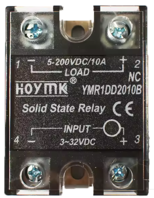
Pin Configuration and Descriptions
| Pin Number | Name | Description |
|---|---|---|
| 1 | Input (+) | Positive terminal for the control voltage (3-32VDC). |
| 2 | Input (-) | Negative terminal for the control voltage (ground). |
| 3 | Load (+) | Positive terminal for the DC load (5-200VDC). |
| 4 | Load (-) | Negative terminal for the DC load (ground). |
Usage Instructions
How to Use the Component in a Circuit
- Power the Control Input: Connect a DC voltage source (3-32VDC) to the input terminals (Pin 1 and Pin 2). Ensure the polarity is correct.
- Connect the Load: Attach the DC load to the load terminals (Pin 3 and Pin 4). The load voltage must be within the range of 5-200VDC, and the current should not exceed 25A.
- Mounting: Secure the relay to a heat-dissipating surface or panel using screws. Proper heat dissipation is critical for high-current applications.
- Switching: When the control voltage is applied, the relay will switch the load circuit ON. Removing the control voltage will turn the load circuit OFF.
Important Considerations and Best Practices
- Heat Dissipation: For high-current applications, use a heatsink or cooling fan to prevent overheating.
- Input Voltage Range: Ensure the control voltage remains within the specified range (3-32VDC) to avoid damage.
- Load Protection: Use appropriate fuses or circuit breakers to protect the load and relay from overcurrent conditions.
- Polarity: Double-check the polarity of both the input and load connections to prevent malfunction or damage.
- Isolation: Maintain proper isolation between the control and load circuits to ensure safety.
Example: Connecting to an Arduino UNO
The HOYMK YMR1DD2025B can be controlled using an Arduino UNO. Below is an example circuit and code to toggle the relay using a digital output pin.
Circuit Diagram
- Connect the Arduino's digital pin (e.g., D7) to the relay's Input (+) terminal (Pin 1) through a 220-ohm resistor.
- Connect the relay's Input (-) terminal (Pin 2) to the Arduino's GND.
- Connect the DC load to the Load (+) and Load (-) terminals (Pin 3 and Pin 4) of the relay.
Arduino Code
// Define the pin connected to the relay control input
const int relayPin = 7;

void setup() {
  // Set the relay pin as an output
  pinMode(relayPin, OUTPUT);

  // Initialize the relay in the OFF state
  digitalWrite(relayPin, LOW);
}

void loop() {
  // Turn the relay ON
  digitalWrite(relayPin, HIGH);
  delay(5000); // Keep the relay ON for 5 seconds

  // Turn the relay OFF
  digitalWrite(relayPin, LOW);
  delay(5000); // Keep the relay OFF for 5 seconds
}
Note: The 220-ohm resistor limits the current from the Arduino pin to the relay input, protecting the microcontroller.
Troubleshooting and FAQs
Common Issues and Solutions
| Issue | Possible Cause | Solution |
|---|---|---|
| Relay does not switch ON | Insufficient control voltage | Ensure the input voltage is within the 3-32VDC range. |
| Incorrect polarity | Verify the polarity of the input connections. | |
| Faulty relay | Test the relay with a known good power source and load. | |
| Load does not turn OFF | Leakage current in the relay | Check if the load requires a minimum current to fully turn OFF. |
| Incorrect wiring | Verify the load connections (Pin 3 and Pin 4). | |
| Overheating during operation | Excessive load current | Ensure the load current does not exceed 25A. |
| Inadequate heat dissipation | Use a heatsink or cooling fan to manage heat. |
FAQs
Can this relay switch AC loads?
- No, the HOYMK YMR1DD2025B is designed specifically for DC loads within the range of 5-200VDC.
What happens if the input voltage exceeds 32VDC?
- Applying a voltage higher than 32VDC to the input terminals may damage the relay. Always stay within the specified range.
Is the relay suitable for PWM control?
- Yes, the relay can handle high-frequency switching, but ensure the switching frequency does not exceed the relay's response time (≤10ms).
Can I use this relay without a heatsink?
- For low-current applications, a heatsink may not be necessary. However, for currents approaching 25A, proper heat dissipation is essential.
By following this documentation, users can effectively integrate the HOYMK Solid State Relay YMR1DD2025B into their projects for reliable and efficient DC load switching.