
How to Use STM32G474CBT6: Examples, Pinouts, and Specs
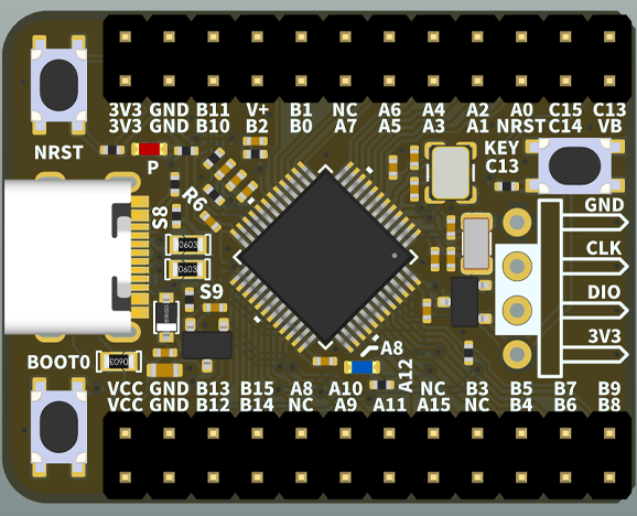
 Design with STM32G474CBT6 in Cirkit Designer
Introduction
The STM32G474CBT6 is a high-performance microcontroller from STMicroelectronics, part of the STM32G4 series. It is built around a 32-bit ARM Cortex-M4 core with a floating-point unit (FPU) and operates at a maximum frequency of 170 MHz. This microcontroller is designed for applications requiring high computational power, precision analog capabilities, and advanced peripherals.
Common applications of the STM32G474CBT6 include:
- Motor control systems
- Industrial automation
- Power conversion and management
- Consumer electronics
- IoT devices and smart sensors
With its rich set of peripherals, including high-resolution timers, multiple ADCs, and communication interfaces, the STM32G474CBT6 is a versatile choice for embedded system developers.
Explore Projects Built with STM32G474CBT6
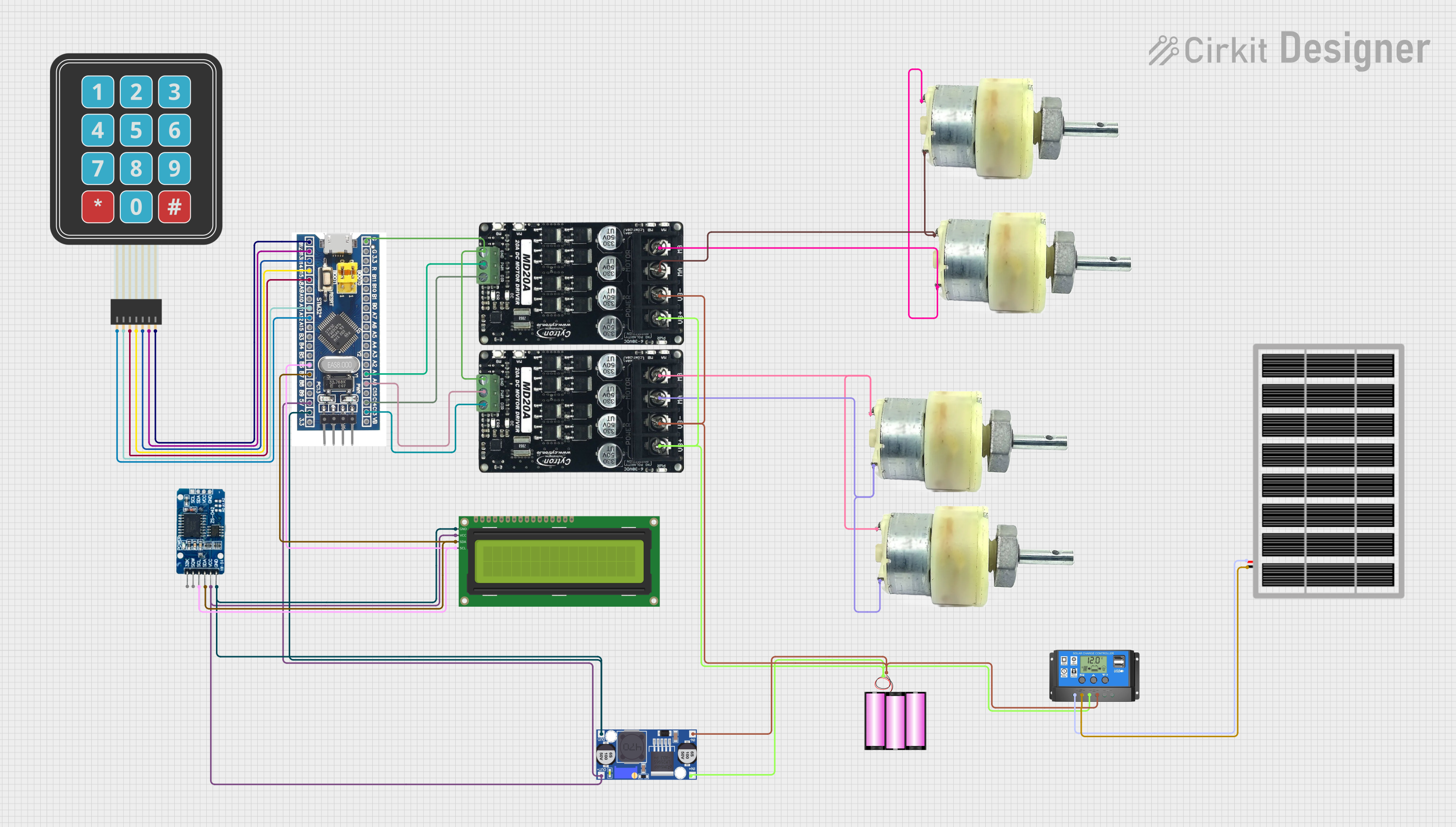 Open Project in Cirkit Designer
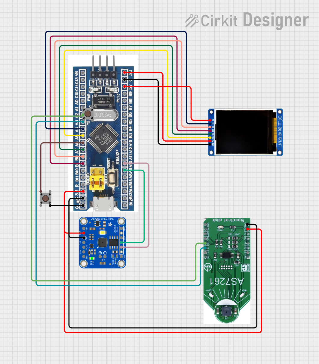 Open Project in Cirkit Designer
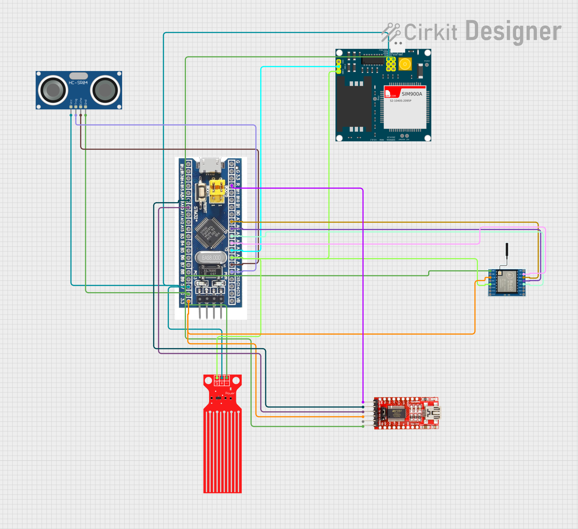 Open Project in Cirkit Designer
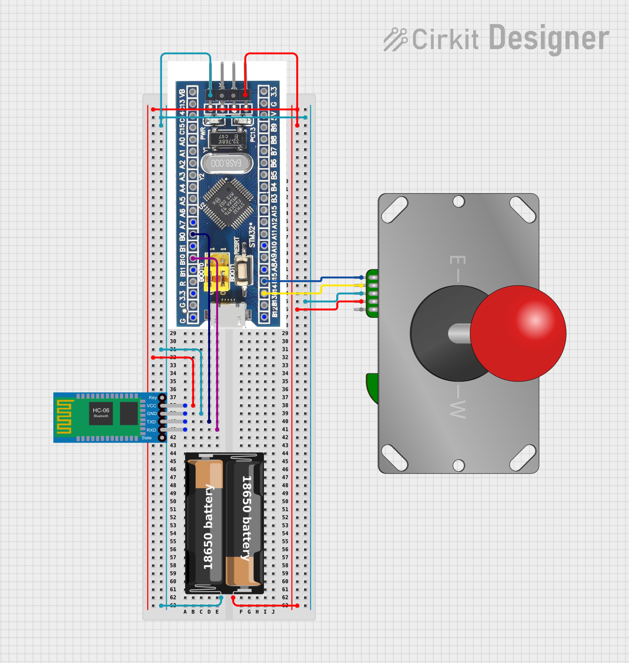 Open Project in Cirkit Designer
Explore Projects Built with STM32G474CBT6
Open Project in Cirkit DesignerOpen Project in Cirkit DesignerOpen Project in Cirkit DesignerOpen Project in Cirkit DesignerTechnical Specifications
Key Technical Details
| Parameter | Value |
|---|---|
| Core | ARM Cortex-M4 with FPU |
| Maximum Clock Speed | 170 MHz |
| Flash Memory | 128 KB |
| SRAM | 32 KB |
| Operating Voltage | 1.7 V to 3.6 V |
| GPIO Pins | Up to 51 |
| ADC | 3x 12-bit ADCs (up to 5 MSPS) |
| DAC | 2x 12-bit DACs |
| Timers | 16 timers (including advanced motor timers) |
| Communication Interfaces | I2C, SPI, USART, CAN, USB, I2S |
| Package | LQFP-48 |
Pin Configuration and Descriptions
The STM32G474CBT6 comes in a 48-pin LQFP package. Below is a summary of key pins and their functions:
| Pin Number | Pin Name | Function(s) | Notes |
|---|---|---|---|
| 1 | VDD | Power Supply | 3.3V typical |
| 2 | VSS | Ground | Connect to ground |
| 3 | PA0 | GPIO/ADC_IN1/USART2_CTS | Multipurpose pin |
| 4 | PA1 | GPIO/ADC_IN2/USART2_RTS | Multipurpose pin |
| 5 | PA2 | GPIO/ADC_IN3/USART2_TX | Multipurpose pin |
| ... | ... | ... | ... |
| 48 | NRST | Reset Input | Active low |
For the full pinout, refer to the STM32G474CBT6 datasheet.
Usage Instructions
How to Use the STM32G474CBT6 in a Circuit
- Power Supply: Provide a stable 3.3V power supply to the VDD pin and connect the VSS pin to ground.
- Clock Configuration: Use an external crystal oscillator or the internal high-speed oscillator (HSI) for clock generation. Configure the clock settings in the firmware.
- GPIO Configuration: Set up GPIO pins as input, output, or alternate function using the STM32 HAL (Hardware Abstraction Layer) or LL (Low Layer) libraries.
- Peripheral Initialization: Enable and configure peripherals such as ADCs, timers, or communication interfaces as needed for your application.
- Programming: Use an ST-Link programmer/debugger to upload firmware via the SWD interface.
Important Considerations and Best Practices
- Decoupling Capacitors: Place decoupling capacitors (e.g., 0.1 µF) close to the VDD pins to ensure stable operation.
- Reset Pin: Connect the NRST pin to a pull-up resistor (e.g., 10 kΩ) to avoid unintended resets.
- Debugging: Reserve the SWD pins (SWCLK and SWDIO) for debugging and programming.
- Clock Accuracy: For applications requiring precise timing, use an external crystal oscillator.
Example: Blinking an LED with STM32G474CBT6 and Arduino IDE
The STM32G474CBT6 can be programmed using the Arduino IDE with the STM32 core installed. Below is an example of blinking an LED connected to pin PA5:
// Include the STM32 HAL library
#include <Arduino.h>

// Define the LED pin
#define LED_PIN PA5

void setup() {
  // Initialize the LED pin as an output
  pinMode(LED_PIN, OUTPUT);
}

void loop() {
  // Turn the LED on
  digitalWrite(LED_PIN, HIGH);
  delay(500); // Wait for 500 ms

  // Turn the LED off
  digitalWrite(LED_PIN, LOW);
  delay(500); // Wait for 500 ms
}
Troubleshooting and FAQs
Common Issues and Solutions
Microcontroller Not Responding
- Cause: Incorrect power supply or missing decoupling capacitors.
- Solution: Verify the power supply voltage (3.3V) and ensure proper decoupling capacitors are in place.
Unable to Program the Microcontroller
- Cause: SWD pins are not accessible or the microcontroller is in a low-power mode.
- Solution: Ensure the SWD pins are connected to the programmer and the microcontroller is not in standby mode.
Peripheral Not Working
- Cause: Incorrect clock configuration or peripheral initialization.
- Solution: Double-check the clock settings and ensure the peripheral is properly initialized in the firmware.
FAQs
Q: Can I use the STM32G474CBT6 with 5V logic?
A: No, the STM32G474CBT6 operates at 3.3V logic levels. Use level shifters if interfacing with 5V devices.
Q: What development tools are compatible with the STM32G474CBT6?
A: You can use STM32CubeIDE, Keil uVision, IAR Embedded Workbench, or the Arduino IDE (with STM32 core).
Q: How do I enable the floating-point unit (FPU)?
A: The FPU is enabled by default in most development environments. Ensure your compiler settings support hardware floating-point operations.
This concludes the documentation for the STM32G474CBT6. For more details, refer to the official datasheet and reference manual from STMicroelectronics.