
How to Use 60mm 8x8 dot matrix row cathode led display with narrow pcb pads: Examples, Pinouts, and Specs
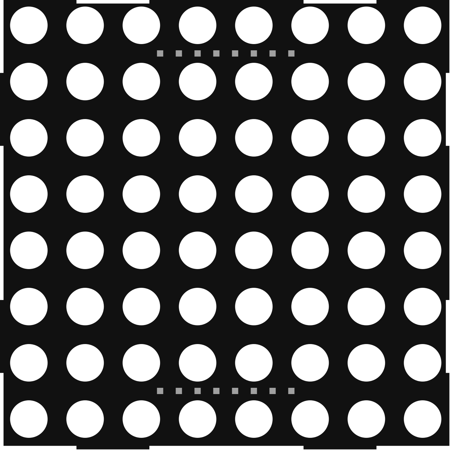
 Design with 60mm 8x8 dot matrix row cathode led display with narrow pcb pads in Cirkit Designer
Introduction
The 60mm 8x8 Dot Matrix Row Cathode LED Display is a compact and versatile module designed for visual output in a variety of electronic applications. It features an 8x8 matrix of LEDs, where each row shares a common cathode. The narrow PCB pads make it easy to solder and integrate into circuits, even in space-constrained designs. This display is ideal for creating alphanumeric characters, symbols, or animations in projects such as digital clocks, counters, message boards, and more.
Explore Projects Built with 60mm 8x8 dot matrix row cathode led display with narrow pcb pads
 Open Project in Cirkit Designer
 Open Project in Cirkit Designer
 Open Project in Cirkit Designer
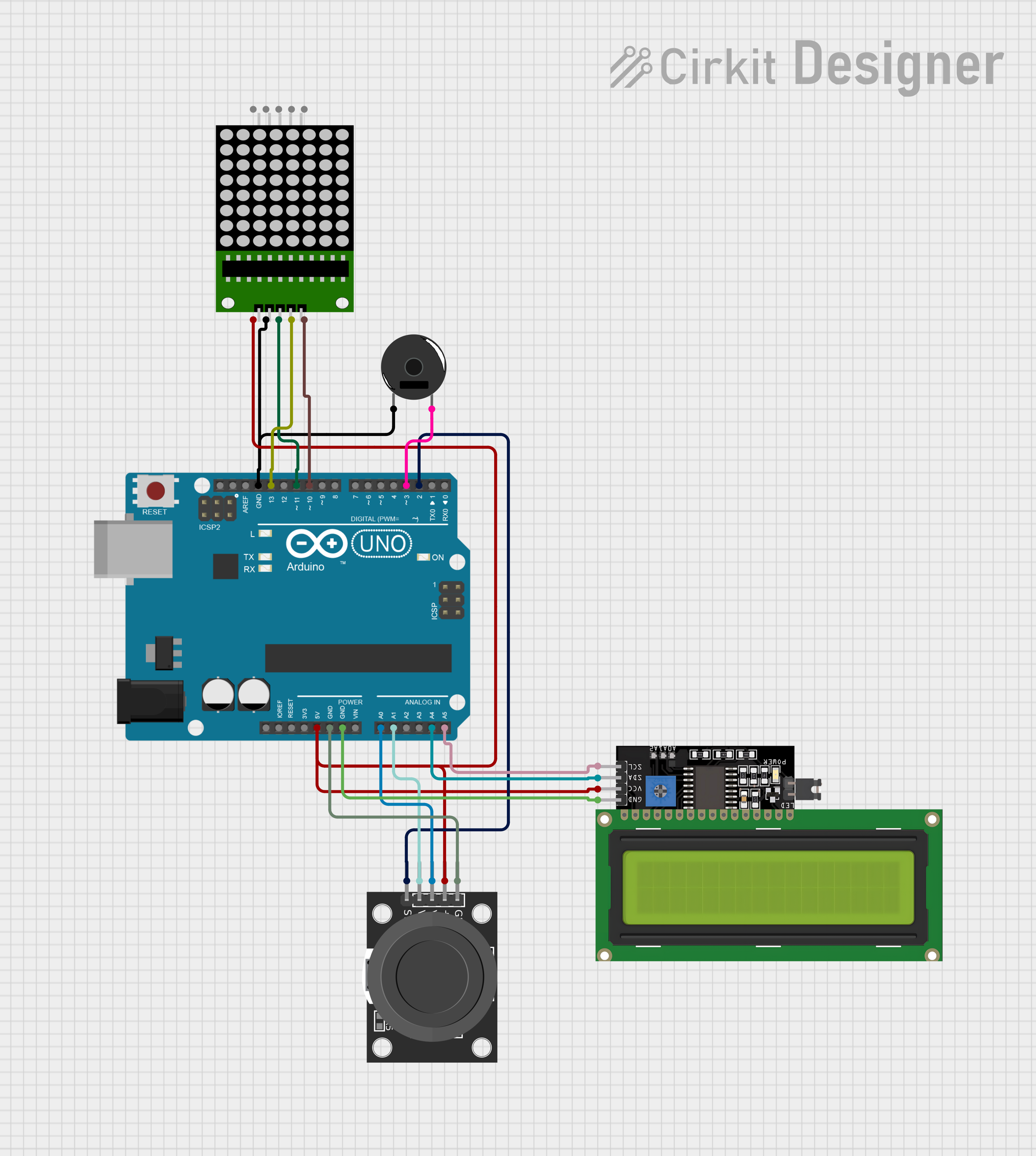 Open Project in Cirkit Designer
Explore Projects Built with 60mm 8x8 dot matrix row cathode led display with narrow pcb pads
Open Project in Cirkit DesignerOpen Project in Cirkit DesignerOpen Project in Cirkit DesignerOpen Project in Cirkit DesignerCommon Applications
- Digital clocks and timers
- Scrolling text displays
- Counters and scoreboards
- DIY electronics projects
- Educational tools for learning about LED matrices
Technical Specifications
Below are the key technical details of the 60mm 8x8 Dot Matrix Row Cathode LED Display:
| Parameter | Value |
|---|---|
| Dimensions | 60mm x 60mm |
| LED Configuration | 8x8 matrix (64 LEDs total) |
| LED Type | Row cathode |
| Forward Voltage (per LED) | 2.0V - 2.2V (typical) |
| Forward Current (per LED) | 20mA (maximum) |
| Peak Wavelength | 625nm (red LEDs, typical) |
| PCB Pad Type | Narrow pads for easy soldering |
| Operating Temperature | -25°C to +85°C |
| Storage Temperature | -40°C to +100°C |
Pin Configuration
The module has 16 pins, with 8 pins corresponding to the rows (cathodes) and 8 pins corresponding to the columns (anodes). Below is the pin configuration:
| Pin Number | Description |
|---|---|
| 1 | Column 1 (Anode) |
| 2 | Column 2 (Anode) |
| 3 | Column 3 (Anode) |
| 4 | Column 4 (Anode) |
| 5 | Column 5 (Anode) |
| 6 | Column 6 (Anode) |
| 7 | Column 7 (Anode) |
| 8 | Column 8 (Anode) |
| 9 | Row 1 (Cathode) |
| 10 | Row 2 (Cathode) |
| 11 | Row 3 (Cathode) |
| 12 | Row 4 (Cathode) |
| 13 | Row 5 (Cathode) |
| 14 | Row 6 (Cathode) |
| 15 | Row 7 (Cathode) |
| 16 | Row 8 (Cathode) |
Usage Instructions
How to Use the Component in a Circuit
- Power Requirements: Ensure that the forward voltage and current ratings of the LEDs are not exceeded. Use current-limiting resistors (typically 220Ω to 330Ω) in series with the anodes to protect the LEDs.
- Driving the Matrix: Use a microcontroller (e.g., Arduino UNO) or a dedicated LED driver IC (e.g., MAX7219) to control the matrix. Multiplexing is required to light up specific LEDs.
- Connections:
- Connect the cathode pins (rows) to the microcontroller or driver IC.
- Connect the anode pins (columns) to the microcontroller or driver IC through current-limiting resistors.
Example: Connecting to an Arduino UNO
Below is an example of how to control the 8x8 LED matrix using an Arduino UNO and multiplexing:
Circuit Connections
- Connect the row pins (cathodes) to Arduino digital pins 2 to 9.
- Connect the column pins (anodes) to Arduino digital pins 10 to 17 through 220Ω resistors.
Arduino Code Example
// Define row and column pins
const int rowPins[8] = {2, 3, 4, 5, 6, 7, 8, 9}; // Cathode pins
const int colPins[8] = {10, 11, 12, 13, A0, A1, A2, A3}; // Anode pins

void setup() {
  // Set all row and column pins as outputs
  for (int i = 0; i < 8; i++) {
    pinMode(rowPins[i], OUTPUT);
    pinMode(colPins[i], OUTPUT);
  }
}

void loop() {
  // Example: Light up LED at Row 1, Column 1
  for (int i = 0; i < 8; i++) {
    digitalWrite(rowPins[i], HIGH); // Turn off all rows
  }
  digitalWrite(rowPins[0], LOW);    // Enable Row 1 (cathode)
  digitalWrite(colPins[0], HIGH);  // Enable Column 1 (anode)
  delay(500);                      // Keep LED on for 500ms

  // Turn off the LED
  digitalWrite(colPins[0], LOW);   // Disable Column 1
  digitalWrite(rowPins[0], HIGH); // Disable Row 1
  delay(500);                      // Wait for 500ms
}
Important Considerations
- Multiplexing: To display multiple LEDs simultaneously, implement multiplexing in your code. This involves rapidly switching between rows and columns to create the illusion of a persistent display.
- Current Limiting: Always use resistors to limit the current through the LEDs and prevent damage.
- Power Supply: Ensure your power supply can handle the total current draw of the matrix.
Troubleshooting and FAQs
Common Issues
LEDs Not Lighting Up:
- Check the connections and ensure the pins are correctly wired.
- Verify that the current-limiting resistors are in place and of appropriate value.
- Ensure the microcontroller or driver IC is functioning properly.
Dim LEDs:
- Verify that the power supply provides sufficient voltage and current.
- Check for loose or poor solder joints on the PCB pads.
Flickering LEDs:
- Ensure proper multiplexing timing in your code.
- Verify that the microcontroller's output pins are not overloaded.
Overheating:
- Check that the current through each LED does not exceed 20mA.
- Use resistors with appropriate power ratings.
FAQs
Q: Can I use this module with a 3.3V microcontroller?
A: Yes, but ensure that the forward voltage of the LEDs is met. You may need to adjust the resistor values accordingly.
Q: How do I display characters or symbols?
A: Use a lookup table in your code to map characters or symbols to specific row and column combinations.
Q: Can I chain multiple matrices together?
A: Yes, but you will need a driver IC like the MAX7219 to simplify control and reduce the number of required microcontroller pins.
Q: What is the best way to solder the narrow PCB pads?
A: Use a fine-tipped soldering iron and thin solder wire. Apply flux to ensure clean and reliable connections.
By following this documentation, you can effectively integrate and use the 60mm 8x8 Dot Matrix Row Cathode LED Display in your projects!