
How to Use LIS302DL: Examples, Pinouts, and Specs

 Design with LIS302DL in Cirkit Designer
Introduction
The LIS302DL is a low-power, three-axis accelerometer designed to measure acceleration along the X, Y, and Z axes. It features a digital output interface (SPI or I²C) for easy integration with microcontrollers and other digital systems. With its compact size and low power consumption, the LIS302DL is ideal for applications such as motion detection, tilt sensing, orientation tracking, and vibration monitoring. Its high sensitivity and configurable data rates make it suitable for a wide range of consumer electronics, industrial, and IoT applications.
Explore Projects Built with LIS302DL
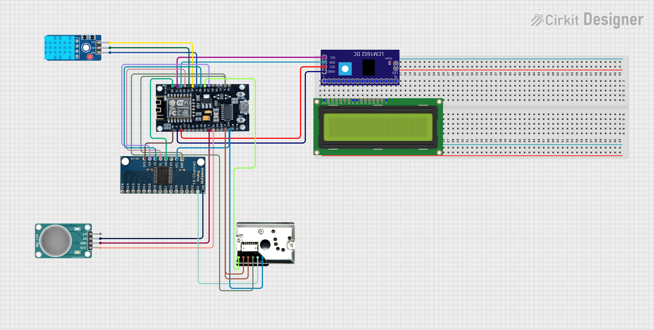 Open Project in Cirkit Designer
 Open Project in Cirkit Designer
 Open Project in Cirkit Designer
 Open Project in Cirkit Designer
Explore Projects Built with LIS302DL
Open Project in Cirkit DesignerOpen Project in Cirkit DesignerOpen Project in Cirkit DesignerOpen Project in Cirkit DesignerTechnical Specifications
The following table outlines the key technical details of the LIS302DL:
| Parameter | Value |
|---|---|
| Operating Voltage | 2.16 V to 3.6 V |
| Current Consumption | 1 µA in power-down mode, |
| 300 µA in active mode | |
| Measurement Range | ±2g or ±8g (selectable) |
| Sensitivity | 18 mg/digit (±2g mode) |
| 72 mg/digit (±8g mode) | |
| Output Interface | SPI (4-wire) or I²C |
| Data Rate | 100 Hz or 400 Hz |
| Operating Temperature | -40°C to +85°C |
| Package Type | LGA-14 (4x4x1.5 mm) |
Pin Configuration and Descriptions
The LIS302DL is housed in a 14-pin LGA package. The pin configuration is as follows:
| Pin Number | Pin Name | Description |
|---|---|---|
| 1 | VDD | Power supply (2.16 V to 3.6 V) |
| 2 | GND | Ground |
| 3 | SCL/SPC | I²C clock / SPI serial port clock |
| 4 | SDA/SDI/SDO | I²C data / SPI data input/output |
| 5 | CS | SPI chip select (active low) |
| 6 | INT1 | Interrupt 1 output |
| 7 | INT2 | Interrupt 2 output |
| 8-14 | NC | Not connected (leave unconnected) |
Usage Instructions
How to Use the LIS302DL in a Circuit
- Power Supply: Connect the VDD pin to a 2.16 V to 3.6 V power source and the GND pin to ground.
- Communication Interface: Choose between SPI or I²C for communication:
- For SPI, connect the SCL/SPC, SDA/SDI/SDO, and CS pins to the corresponding SPI pins on your microcontroller.
- For I²C, connect the SCL/SPC and SDA/SDI/SDO pins to the I²C clock and data lines, respectively. Use pull-up resistors (typically 4.7 kΩ) on these lines.
- Interrupts: Optionally, connect the INT1 and/or INT2 pins to microcontroller GPIO pins to handle interrupts for motion detection or other events.
- Bypass Unused Pins: Leave the NC pins unconnected.
Important Considerations and Best Practices
- Decoupling Capacitor: Place a 0.1 µF ceramic capacitor close to the VDD pin to reduce power supply noise.
- Mounting Orientation: Ensure the accelerometer is mounted correctly to measure acceleration along the desired axes.
- Configuration: Use the control registers to configure the measurement range, data rate, and interrupt settings.
- Startup Time: Allow a short delay (typically a few milliseconds) after power-up for the device to initialize.
Example Code for Arduino UNO
Below is an example of how to interface the LIS302DL with an Arduino UNO using the SPI interface:
#include <SPI.h>

// Define SPI pins for LIS302DL
const int CS_PIN = 10; // Chip Select pin

// LIS302DL register addresses
#define WHO_AM_I 0x0F
#define CTRL_REG1 0x20
#define OUT_X 0x29
#define OUT_Y 0x2B
#define OUT_Z 0x2D

void setup() {
  // Initialize serial communication
  Serial.begin(9600);

  // Configure SPI settings
  SPI.begin();
  SPI.setDataMode(SPI_MODE3); // LIS302DL uses SPI mode 3
  SPI.setClockDivider(SPI_CLOCK_DIV16); // Set SPI clock speed
  pinMode(CS_PIN, OUTPUT);
  digitalWrite(CS_PIN, HIGH); // Deselect the LIS302DL

  // Initialize LIS302DL
  writeRegister(CTRL_REG1, 0x47); // Enable all axes, set data rate to 100 Hz
  Serial.println("LIS302DL initialized.");
}

void loop() {
  // Read acceleration data
  int8_t x = readRegister(OUT_X);
  int8_t y = readRegister(OUT_Y);
  int8_t z = readRegister(OUT_Z);

  // Print acceleration values
  Serial.print("X: ");
  Serial.print(x);
  Serial.print(" Y: ");
  Serial.print(y);
  Serial.print(" Z: ");
  Serial.println(z);

  delay(500); // Wait for 500 ms
}

// Function to write to a register
void writeRegister(byte reg, byte value) {
  digitalWrite(CS_PIN, LOW); // Select the LIS302DL
  SPI.transfer(reg);
  SPI.transfer(value);
  digitalWrite(CS_PIN, HIGH); // Deselect the LIS302DL
}

// Function to read from a register
byte readRegister(byte reg) {
  digitalWrite(CS_PIN, LOW); // Select the LIS302DL
  SPI.transfer(reg | 0x80); // Set MSB to 1 for read operation
  byte value = SPI.transfer(0x00); // Read the register value
  digitalWrite(CS_PIN, HIGH); // Deselect the LIS302DL
  return value;
}
Troubleshooting and FAQs
Common Issues
No Output Data:
- Ensure the LIS302DL is powered correctly and the VDD and GND pins are connected.
- Verify that the communication interface (SPI or I²C) is configured properly.
- Check if the control registers are set up correctly to enable the desired axes and data rate.
Incorrect or Noisy Readings:
- Verify the mounting orientation of the accelerometer.
- Ensure the decoupling capacitor is placed close to the VDD pin.
- Check for excessive noise on the power supply or communication lines.
Interrupts Not Triggering:
- Confirm that the interrupt pins (INT1/INT2) are connected to the microcontroller.
- Verify the interrupt configuration in the control registers.
Tips for Troubleshooting
- Use a logic analyzer or oscilloscope to monitor the SPI or I²C signals for debugging communication issues.
- Refer to the LIS302DL datasheet for detailed register descriptions and configuration options.
- Test the accelerometer with a simple setup before integrating it into a complex system.