How to Use BC547 Transistor: Examples, Pinouts, and Specs
Introduction
The BC547 is a general-purpose NPN bipolar junction transistor (BJT) widely used in low-power amplification and switching applications. It is a reliable and versatile component, making it a popular choice for hobbyists and professionals alike. With a maximum collector current of 100 mA and a voltage rating of 45 V, the BC547 is suitable for a variety of electronic circuits, including signal amplification, small motor control, and digital switching.
Explore Projects Built with BC547 Transistor
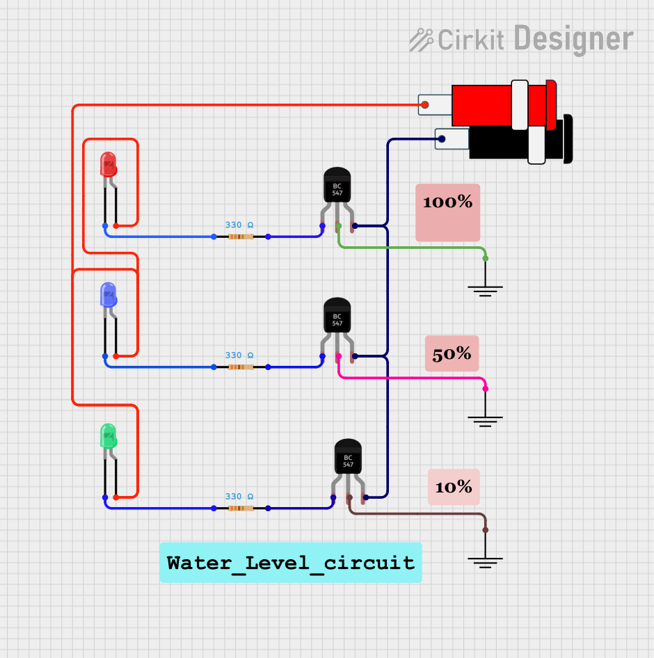
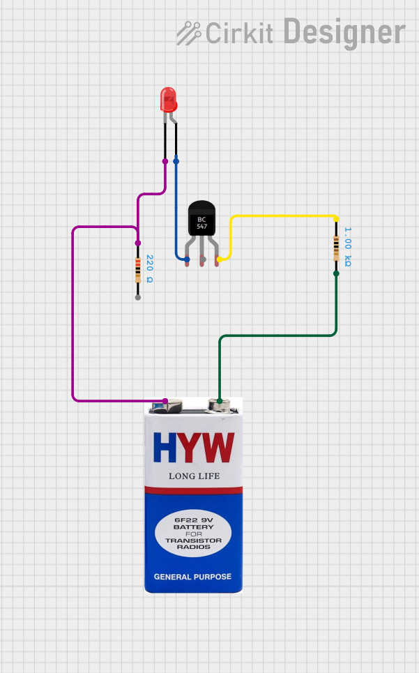
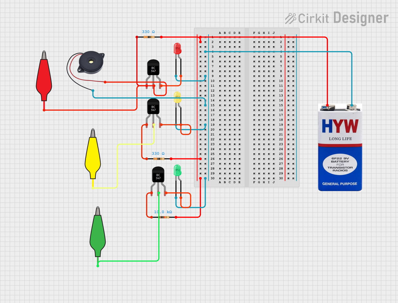
Explore Projects Built with BC547 Transistor
Common Applications:
- Signal amplification in audio and RF circuits
- Switching small loads such as LEDs or relays
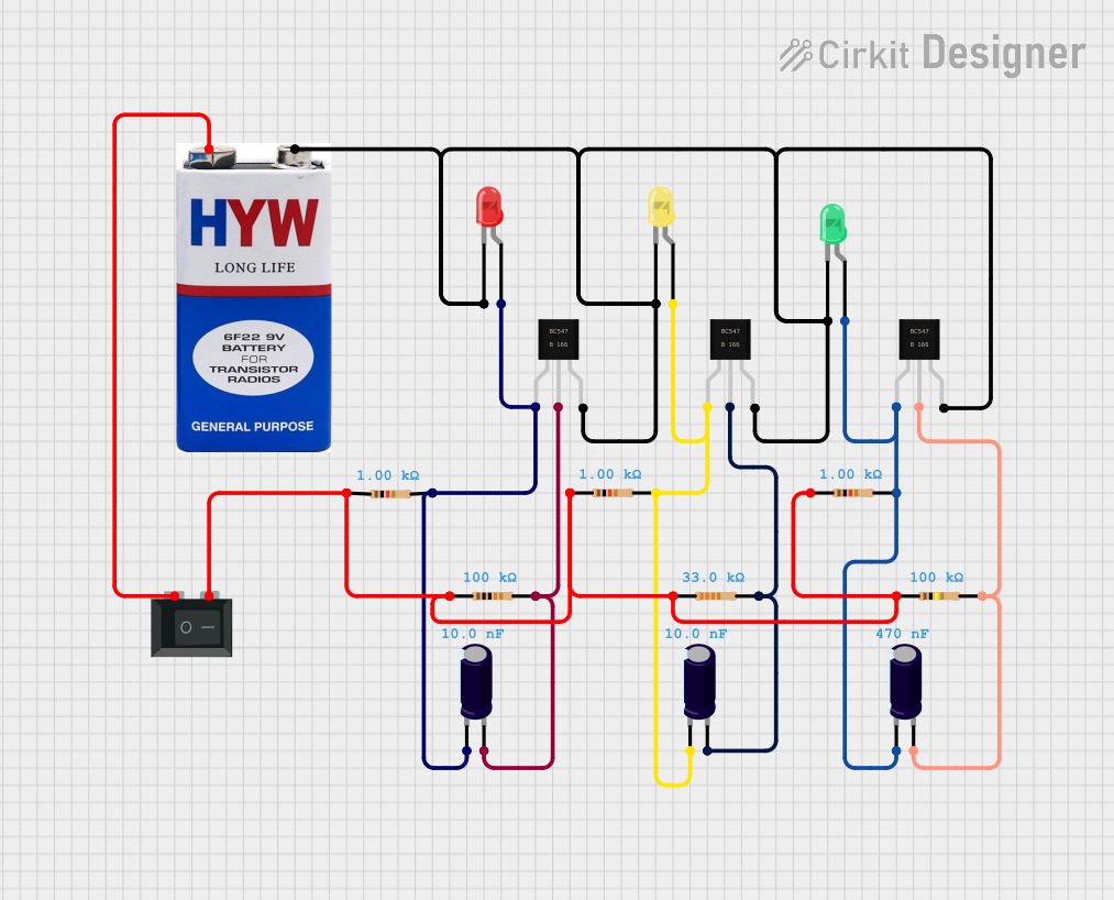
- Oscillator circuits
- Voltage regulation and current limiting
- General-purpose low-power applications
Technical Specifications
Below are the key technical details of the BC547 transistor:
| Parameter | Value |
|---|---|
| Transistor Type | NPN |
| Maximum Collector Current (Ic) | 100 mA |
| Maximum Collector-Emitter Voltage (Vce) | 45 V |
| Maximum Collector-Base Voltage (Vcb) | 50 V |
| Maximum Emitter-Base Voltage (Veb) | 6 V |
| DC Current Gain (hFE) | 110 to 800 (varies by model) |
| Power Dissipation (Ptot) | 500 mW |
| Transition Frequency (ft) | 150 MHz |
| Package Type | TO-92 |
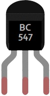
Pin Configuration
The BC547 transistor comes in a TO-92 package with three pins. The pinout is as follows:
| Pin Number | Pin Name | Description |
|---|---|---|
| 1 | Collector | Current flows out of this pin. |
| 2 | Base | Controls the transistor's operation. |
| 3 | Emitter | Current flows into this pin. |
The pinout diagram for the BC547 (TO-92 package) is shown below:
   _______
  |       |
  |       |
  |_______|
   | | |
   1 2 3
   C B E
Usage Instructions
How to Use the BC547 in a Circuit
Determine the Configuration: The BC547 can be used in three configurations:
- Common Emitter: For amplification and switching.
- Common Base: For high-frequency applications.
- Common Collector: For impedance matching.
Biasing the Transistor:
- To operate the BC547 in the active region (for amplification), apply a small current to the base pin. Ensure the base-emitter voltage (Vbe) is approximately 0.7 V.
- For switching applications, drive the base pin with sufficient current to saturate the transistor.
Connect the Load:
- For switching, connect the load (e.g., LED, relay) to the collector pin.
- Use a current-limiting resistor in series with the base pin to prevent damage.
Calculate Resistor Values:
- Base Resistor (Rb): Use Ohm's law to calculate the resistor value based on the input voltage and required base current.
- Example: If the input voltage is 5 V and the base current is 5 mA, Rb = (5 V - 0.7 V) / 5 mA = 860 Ω.
Example Circuit with Arduino UNO
The BC547 can be used to control an LED with an Arduino UNO. Below is an example circuit and code:
Circuit Description:
- The base of the BC547 is connected to a digital pin of the Arduino through a 1 kΩ resistor.
- The collector is connected to the positive terminal of the LED.
- The emitter is connected to ground.
- A 220 Ω resistor is connected in series with the LED to limit current.
Arduino Code:
// Define the pin connected to the BC547 base
const int transistorBasePin = 9; // Digital pin 9

void setup() {
  pinMode(transistorBasePin, OUTPUT); // Set pin as output
}

void loop() {
  digitalWrite(transistorBasePin, HIGH); // Turn on the transistor
  delay(1000); // Keep the LED on for 1 second
  digitalWrite(transistorBasePin, LOW);  // Turn off the transistor
  delay(1000); // Keep the LED off for 1 second
}
Important Considerations:
- Do not exceed the maximum ratings for voltage, current, or power dissipation.
- Always use a base resistor to limit the base current.
- Ensure proper heat dissipation if the transistor operates near its maximum power rating.
Troubleshooting and FAQs
Common Issues and Solutions:
Transistor Not Switching Properly:
- Cause: Insufficient base current.
- Solution: Check the base resistor value and ensure the base current is adequate.
Overheating:
- Cause: Exceeding the power dissipation limit.
- Solution: Reduce the load current or use a heat sink.
No Output Signal:
- Cause: Incorrect pin connections.
- Solution: Verify the pinout and ensure proper wiring.
LED Not Lighting Up in Example Circuit:
- Cause: Incorrect resistor values or damaged components.
- Solution: Double-check the resistor values and test the LED and transistor.
FAQs:
Q1: Can the BC547 handle high-power loads?
A1: No, the BC547 is designed for low-power applications with a maximum collector current of 100 mA. For high-power loads, consider using a power transistor like the TIP120.
Q2: What is the difference between BC547A, BC547B, and BC547C?
A2: The difference lies in their DC current gain (hFE) range:
- BC547A: 110 to 220
- BC547B: 200 to 450
- BC547C: 420 to 800
Q3: Can I use the BC547 for audio amplification?
A3: Yes, the BC547 is suitable for small-signal audio amplification.
Q4: What is the maximum frequency the BC547 can handle?
A4: The BC547 has a transition frequency (ft) of 150 MHz, making it suitable for high-frequency applications within this range.