How to Use ESP32 S3 CAM: Examples, Pinouts, and Specs
Introduction
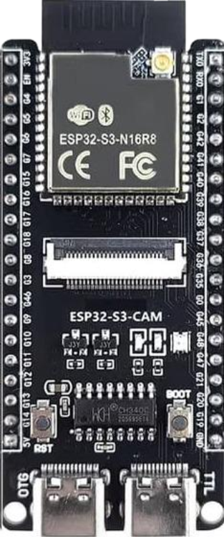
The ESP32-S3-CAM is a low-cost, low-power system on a chip (SoC) that integrates Wi-Fi and Bluetooth capabilities, along with a camera interface for image and video capture. It is based on the ESP32-S3 microcontroller, which features a dual-core Xtensa LX7 processor, making it ideal for IoT applications, smart devices, and AI-powered image processing tasks. The ESP32-S3-CAM is widely used in projects requiring wireless connectivity and visual data processing, such as home automation, surveillance systems, and robotics.
Explore Projects Built with ESP32 S3 CAM


Explore Projects Built with ESP32 S3 CAM
Common Applications
- Smart home security cameras
- IoT-enabled image recognition systems
- Wireless video streaming devices
- AI-based object detection and tracking
- Robotics and automation systems
Technical Specifications
Key Technical Details
| Parameter | Specification |
|---|---|
| Microcontroller | ESP32-S3 (Xtensa LX7 dual-core processor) |
| Clock Speed | Up to 240 MHz |
| Flash Memory | 8 MB (varies by model) |
| RAM | 512 KB SRAM + 2 MB PSRAM |
| Wireless Connectivity | Wi-Fi 802.11 b/g/n, Bluetooth 5.0 (LE) |
| Camera Interface | Supports OV2640 and OV3660 cameras |
| GPIO Pins | 44 (multiplexed with other functions) |
| Operating Voltage | 3.3V |
| Power Consumption | Ultra-low power (varies by use case) |
| Image Processing | AI acceleration with vector instructions |
| Dimensions | Compact module (varies by manufacturer) |
Pin Configuration and Descriptions
The ESP32-S3-CAM module typically includes a set of GPIO pins, a camera interface, and other peripherals. Below is a general pinout description:
| Pin Name | Function | Description |
|---|---|---|
| 3V3 | Power Supply | 3.3V input for powering the module |
| GND | Ground | Common ground for the circuit |
| GPIO0 | Boot Mode Selection | Used for flashing firmware |
| GPIO1 | UART TX | Serial communication (transmit) |
| GPIO3 | UART RX | Serial communication (receive) |
| GPIO13 | Camera Data Line | Data input from the camera |
| GPIO14 | Camera Data Line | Data input from the camera |
| GPIO15 | Camera Clock | Clock signal for the camera |
| GPIO16 | Camera Reset | Resets the camera module |
| GPIO17 | Camera Power Down | Powers down the camera module |
| GPIO18 | I2C SCL | I2C clock line for camera configuration |
| GPIO19 | I2C SDA | I2C data line for camera configuration |
| GPIO21 | LED Flash Control | Controls the onboard LED flash |
Note: Pin configurations may vary slightly depending on the specific ESP32-S3-CAM module. Always refer to the manufacturer's datasheet for exact details.
Usage Instructions
How to Use the ESP32-S3-CAM in a Circuit
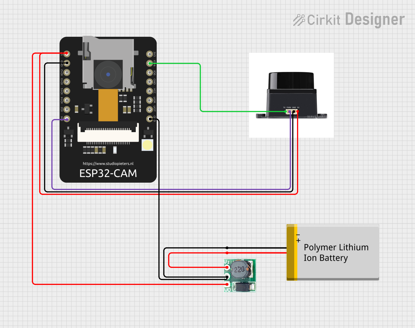
- Power Supply: Connect the 3V3 pin to a stable 3.3V power source and GND to ground.
- Camera Connection: Attach a compatible camera module (e.g., OV2640) to the designated camera interface pins.
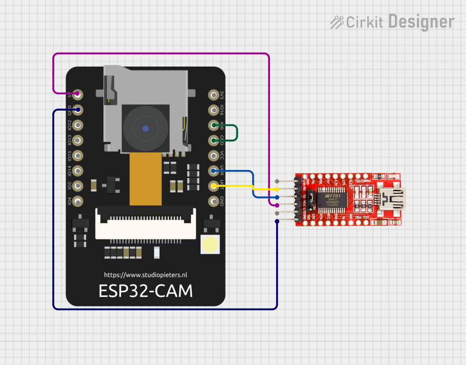
- Flashing Firmware:
- Connect GPIO0 to GND to enable boot mode.
- Use a USB-to-serial adapter to connect the UART TX and RX pins to your computer.
- Flash the firmware using the ESP-IDF or Arduino IDE.
- Wi-Fi and Bluetooth Setup: Configure the wireless settings in your firmware to enable connectivity.
- GPIO Usage: Use the remaining GPIO pins for additional peripherals like sensors, actuators, or LEDs.
Important Considerations and Best Practices
- Power Supply: Ensure a stable 3.3V power source to avoid damage to the module.
- Heat Management: The ESP32-S3-CAM can generate heat during operation. Use proper ventilation or a heatsink if necessary.
- Firmware Compatibility: Use the latest ESP-IDF or Arduino core for ESP32-S3 to ensure compatibility with the module's features.
- Camera Selection: Verify that the camera module is compatible with the ESP32-S3-CAM (e.g., OV2640 or OV3660).
- Antenna Placement: For optimal Wi-Fi performance, ensure the onboard antenna is not obstructed by metal or other conductive materials.
Example Code for Arduino IDE
Below is an example of how to capture an image using the ESP32-S3-CAM and stream it over Wi-Fi:
#include <WiFi.h>
#include <esp_camera.h>

// Replace with your Wi-Fi credentials
const char* ssid = "Your_SSID";
const char* password = "Your_PASSWORD";

// Camera configuration
#define PWDN_GPIO_NUM    -1
#define RESET_GPIO_NUM   -1
#define XCLK_GPIO_NUM    0
#define SIOD_GPIO_NUM    18
#define SIOC_GPIO_NUM    19
#define Y9_GPIO_NUM      13
#define Y8_GPIO_NUM      14
#define Y7_GPIO_NUM      15
#define Y6_GPIO_NUM      16
#define Y5_GPIO_NUM      17
#define Y4_GPIO_NUM      21
#define Y3_GPIO_NUM      36
#define Y2_GPIO_NUM      39
#define VSYNC_GPIO_NUM   5
#define HREF_GPIO_NUM    27
#define PCLK_GPIO_NUM    25

void setup() {
  Serial.begin(115200);

  // Connect to Wi-Fi
  WiFi.begin(ssid, password);
  while (WiFi.status() != WL_CONNECTED) {
    delay(500);
    Serial.print(".");
  }
  Serial.println("\nWi-Fi connected");

  // Initialize the camera
  camera_config_t config;
  config.ledc_channel = LEDC_CHANNEL_0;
  config.ledc_timer = LEDC_TIMER_0;
  config.pin_d0 = Y2_GPIO_NUM;
  config.pin_d1 = Y3_GPIO_NUM;
  config.pin_d2 = Y4_GPIO_NUM;
  config.pin_d3 = Y5_GPIO_NUM;
  config.pin_d4 = Y6_GPIO_NUM;
  config.pin_d5 = Y7_GPIO_NUM;
  config.pin_d6 = Y8_GPIO_NUM;
  config.pin_d7 = Y9_GPIO_NUM;
  config.pin_xclk = XCLK_GPIO_NUM;
  config.pin_pclk = PCLK_GPIO_NUM;
  config.pin_vsync = VSYNC_GPIO_NUM;
  config.pin_href = HREF_GPIO_NUM;
  config.pin_sscb_sda = SIOD_GPIO_NUM;
  config.pin_sscb_scl = SIOC_GPIO_NUM;
  config.pin_pwdn = PWDN_GPIO_NUM;
  config.pin_reset = RESET_GPIO_NUM;
  config.xclk_freq_hz = 20000000;
  config.pixel_format = PIXFORMAT_JPEG;

  if (esp_camera_init(&config) != ESP_OK) {
    Serial.println("Camera initialization failed");
    return;
  }
  Serial.println("Camera initialized successfully");
}

void loop() {
  // Capture an image
  camera_fb_t* fb = esp_camera_fb_get();
  if (!fb) {
    Serial.println("Failed to capture image");
    return;
  }

  Serial.printf("Captured image with size: %d bytes\n", fb->len);
  esp_camera_fb_return(fb);

  delay(5000); // Wait 5 seconds before capturing the next image
}
Troubleshooting and FAQs
Common Issues
Camera Initialization Failed:
- Ensure the camera is properly connected to the module.
- Verify that the camera model is compatible with the ESP32-S3-CAM.
- Check the pin configuration in your code.
Wi-Fi Connection Issues:
- Double-check the SSID and password in your code.
- Ensure the Wi-Fi signal strength is sufficient.
Module Overheating:
- Use proper ventilation or a heatsink to dissipate heat.
- Avoid running the module at maximum performance for extended periods.
Firmware Flashing Errors:
- Ensure GPIO0 is connected to GND during flashing.
- Use a reliable USB-to-serial adapter and verify the COM port settings.
FAQs
Q: Can I use a different camera module with the ESP32-S3-CAM?
A: The ESP32-S3-CAM supports OV2640 and OV3660 cameras. Other cameras may require additional drivers or modifications.
Q: How do I reset the module?
A: You can reset the module by toggling the RESET pin or by power cycling the device.
Q: Can the ESP32-S3-CAM stream video?
A: Yes, the module can stream video over Wi-Fi, but the frame rate and resolution depend on the network bandwidth and processing power.
Q: Is the ESP32-S3-CAM compatible with the Arduino IDE?
A: Yes, the ESP32-S3-CAM is fully supported by the Arduino IDE with the appropriate ESP32 board package installed.