
How to Use MCP7384XX: Examples, Pinouts, and Specs
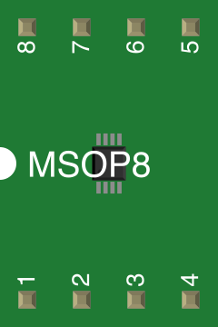
 Design with MCP7384XX in Cirkit Designer
Introduction
The MCP7384XX is a highly integrated Li-Ion/Li-Polymer battery charge management controller designed to provide a complete charging solution for single-cell batteries. It employs a linear charge management architecture, ensuring efficient charging with minimal external components. The device includes advanced features such as thermal regulation, automatic recharge, and charge status indication, making it ideal for portable and compact applications.
Explore Projects Built with MCP7384XX
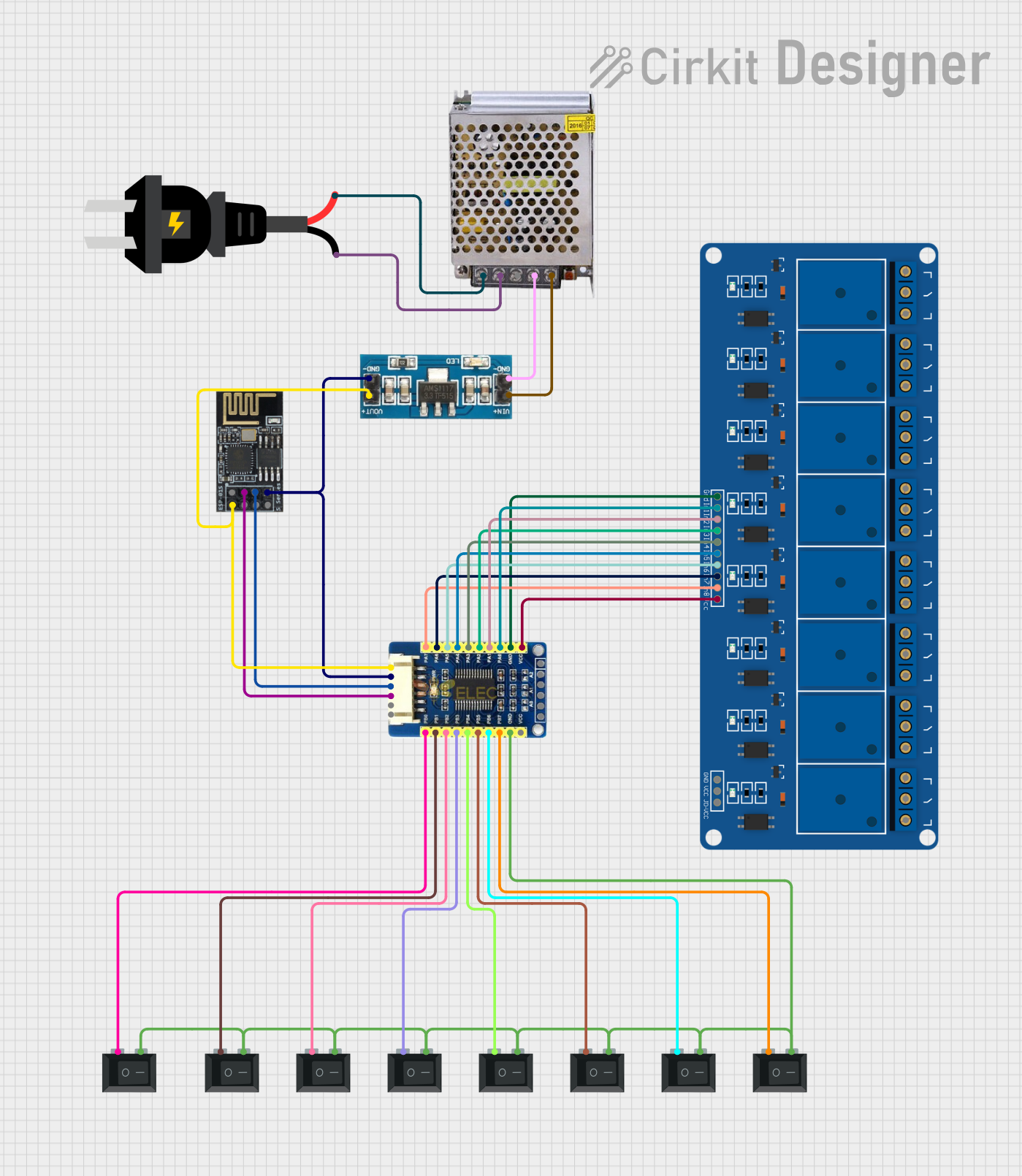 Open Project in Cirkit Designer
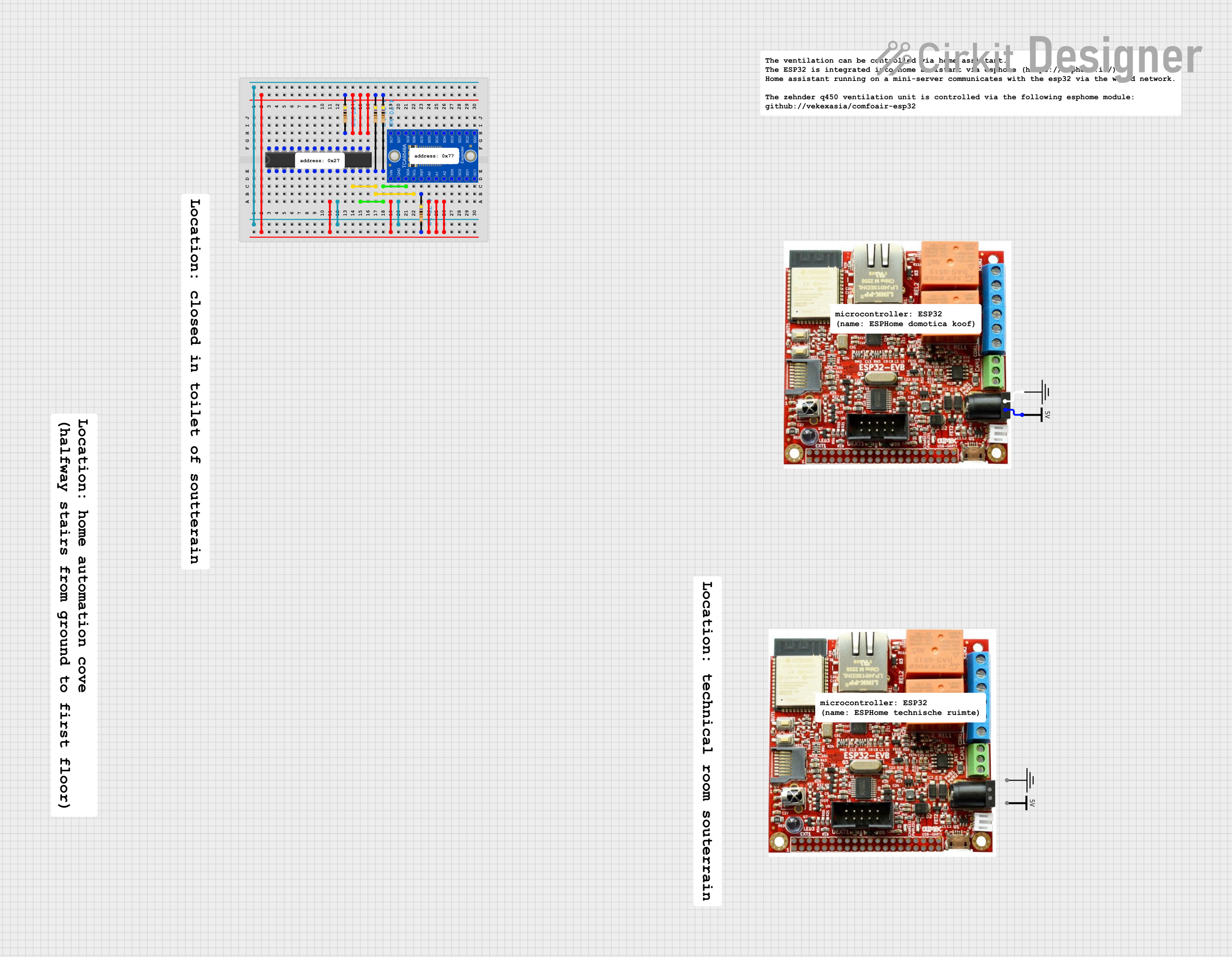 Open Project in Cirkit Designer
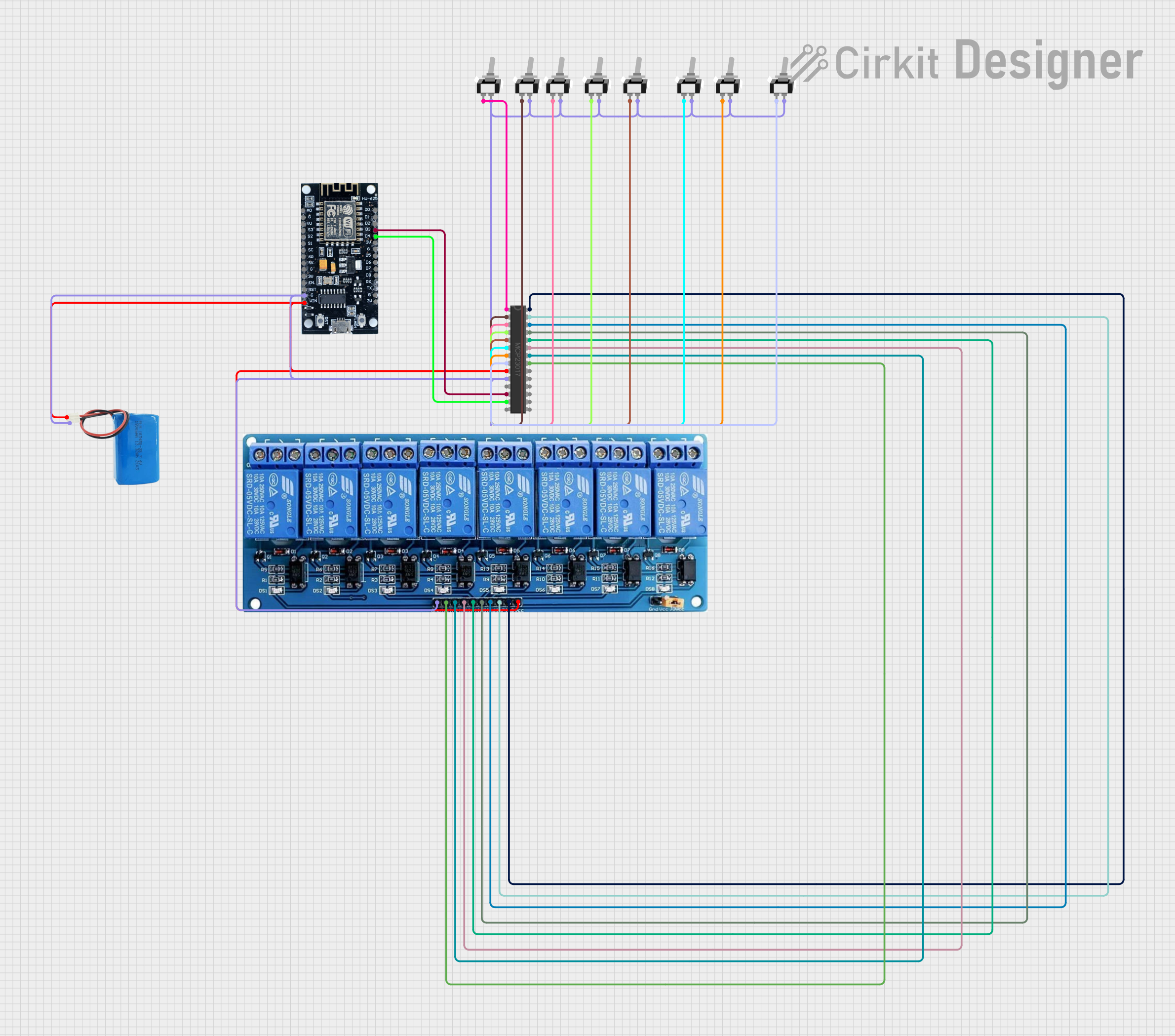 Open Project in Cirkit Designer
 Open Project in Cirkit Designer
Explore Projects Built with MCP7384XX
Open Project in Cirkit DesignerOpen Project in Cirkit DesignerOpen Project in Cirkit DesignerOpen Project in Cirkit DesignerCommon Applications
- Smartphones and tablets
- Wearable devices
- Portable medical equipment
- Power banks
- Wireless sensors and IoT devices
Technical Specifications
Key Technical Details
| Parameter | Value |
|---|---|
| Input Voltage Range | 3.75V to 6V |
| Battery Regulation Voltage | 4.2V (typical) |
| Charge Current | Programmable up to 1A |
| Thermal Regulation | 85°C (typical) |
| Automatic Recharge | Yes |
| Charge Termination | -0.7% of programmed current (typical) |
| Status Indication | Two open-drain outputs (charging, charged) |
| Package Options | SOT-23-5, DFN-10 |
Pin Configuration and Descriptions
SOT-23-5 Package
| Pin Number | Pin Name | Description |
|---|---|---|
| 1 | VDD | Input supply voltage (3.75V to 6V). |
| 2 | STAT | Open-drain status output (charging/charged). |
| 3 | PROG | Programs the charge current via resistor. |
| 4 | GND | Ground connection. |
| 5 | VBAT | Battery connection (to positive terminal). |
DFN-10 Package
| Pin Number | Pin Name | Description |
|---|---|---|
| 1 | VDD | Input supply voltage (3.75V to 6V). |
| 2 | STAT1 | Open-drain status output 1 (charging). |
| 3 | STAT2 | Open-drain status output 2 (charged). |
| 4 | PROG | Programs the charge current via resistor. |
| 5 | GND | Ground connection. |
| 6 | VBAT | Battery connection (to positive terminal). |
| 7-10 | NC | No connection (leave floating). |
Usage Instructions
How to Use the MCP7384XX in a Circuit
- Power Supply: Connect the VDD pin to a regulated DC power supply (3.75V to 6V). Ensure the supply voltage is within the specified range to avoid damage.
- Battery Connection: Connect the positive terminal of the Li-Ion/Li-Polymer battery to the VBAT pin. The negative terminal should be connected to GND.
- Programming Charge Current: Use a resistor between the PROG pin and GND to set the desired charge current. The charge current can be calculated using the formula: [ I_{CHARGE} = \frac{1000}{R_{PROG}} ] where ( R_{PROG} ) is in kΩ and ( I_{CHARGE} ) is in mA.
- Status Indication: Connect LEDs (with appropriate current-limiting resistors) to the STAT pins for visual charge status indication:
- STAT1: Charging
- STAT2: Fully charged
- Thermal Considerations: Ensure proper heat dissipation by placing the MCP7384XX on a PCB with adequate thermal vias and copper area.
Example Circuit
Below is a basic circuit diagram for using the MCP7384XX to charge a single-cell Li-Ion battery:
VDD (5V) ----+---- MCP7384XX ----+---- VBAT (Battery Positive)
             |                   |
           R_PROG               GND (Battery Negative)
Arduino Integration
The MCP7384XX can be monitored using an Arduino to read the status pins. Here's an example code snippet:
// Define pin connections for MCP7384XX status pins
const int stat1Pin = 2; // STAT1 connected to Arduino pin 2
const int stat2Pin = 3; // STAT2 connected to Arduino pin 3

void setup() {
  pinMode(stat1Pin, INPUT); // Set STAT1 as input
  pinMode(stat2Pin, INPUT); // Set STAT2 as input
  Serial.begin(9600);       // Initialize serial communication
}

void loop() {
  int stat1 = digitalRead(stat1Pin); // Read STAT1 pin
  int stat2 = digitalRead(stat2Pin); // Read STAT2 pin

  // Check charging status
  if (stat1 == LOW && stat2 == HIGH) {
    Serial.println("Battery is charging...");
  } else if (stat1 == HIGH && stat2 == LOW) {
    Serial.println("Battery is fully charged.");
  } else {
    Serial.println("No battery detected or error.");
  }

  delay(1000); // Wait 1 second before checking again
}
Best Practices
- Use a decoupling capacitor (e.g., 1µF ceramic) close to the VDD pin to stabilize the input voltage.
- Avoid exceeding the maximum input voltage (6V) to prevent damage to the device.
- Ensure the battery is within the supported chemistry (Li-Ion/Li-Polymer) and voltage range.
Troubleshooting and FAQs
Common Issues and Solutions
Device Overheating
- Cause: Insufficient thermal dissipation.
- Solution: Increase the PCB copper area around the MCP7384XX or add thermal vias.
Battery Not Charging
- Cause: Incorrect resistor value on the PROG pin.
- Solution: Verify the resistor value and recalculate the charge current.
Status LEDs Not Working
- Cause: Missing or incorrect current-limiting resistors.
- Solution: Add appropriate resistors (e.g., 1kΩ) in series with the LEDs.
No Output on VBAT Pin
- Cause: Faulty battery connection or damaged MCP7384XX.
- Solution: Check the battery connection and replace the MCP7384XX if necessary.
FAQs
Q1: Can the MCP7384XX charge multiple cells in series?
A1: No, the MCP7384XX is designed for single-cell Li-Ion/Li-Polymer batteries only.
Q2: What happens if the input voltage exceeds 6V?
A2: Exceeding 6V can permanently damage the MCP7384XX. Always use a regulated power supply within the specified range.
Q3: Can I use the MCP7384XX without status LEDs?
A3: Yes, the STAT pins can be left unconnected if status indication is not required.
Q4: How do I calculate the charge termination current?
A4: The charge termination current is typically -0.7% of the programmed charge current. For example, if the charge current is 500mA, the termination current is approximately 3.5mA.