Cirkit Designer Logo
Cirkit Designer
Your all-in-one circuit design IDE
Home / 
Component Documentation

How to Use Traffic Light: Examples, Pinouts, and Specs

Image of Traffic Light
Cirkit Designer LogoDesign with Traffic Light in Cirkit Designer

Introduction

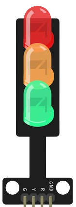
A traffic light is a signaling device that uses colored lights—red, yellow, and green—to control traffic flow at intersections. These lights indicate stop, caution, and go, respectively, ensuring safe and orderly movement of vehicles and pedestrians. Traffic lights are widely used in urban areas, highways, and pedestrian crossings to manage traffic efficiently and reduce accidents.

Explore Projects Built with Traffic Light

Use Cirkit Designer to design, explore, and prototype these projects online. Some projects support real-time simulation. Click "Open Project" to start designing instantly!
Arduino UNO Controlled Traffic Light System
Image of traffic light led: A project utilizing Traffic Light in a practical application
This circuit is designed to simulate a traffic light system using an Arduino UNO microcontroller and a separate traffic light module with green, yellow, and red LEDs. The Arduino sequentially lights up the green, yellow, and red LEDs for 5, 2, and 5 seconds respectively, mimicking the behavior of a standard traffic signal. The code provided for the Arduino manages the timing and switching of the LEDs.
Cirkit Designer LogoOpen Project in Cirkit Designer
Arduino UNO Controlled Traffic Light System
Image of led traffic: A project utilizing Traffic Light in a practical application
This circuit is designed to simulate a traffic light system using an Arduino UNO microcontroller and a set of three LEDs representing the green, yellow, and red lights of a traffic signal. The Arduino is programmed to sequentially turn on the green LED for 5 seconds, the yellow LED for 2 seconds, and the red LED for 5 seconds, with this cycle repeating indefinitely. The LEDs are connected to digital pins D3, D2, and D1 of the Arduino, respectively, and share a common ground.
Cirkit Designer LogoOpen Project in Cirkit Designer
Arduino-Controlled Traffic Light System with Joystick Interface
Image of joystick with traffic led 1: A project utilizing Traffic Light in a practical application
This circuit is designed to simulate a traffic light system controlled by a joystick module, interfaced with an Arduino UNO microcontroller. The joystick's movements dictate the state of the traffic light: moving the joystick up activates the red light, left for yellow, right for green, and down for all lights. The Arduino's digital pins D2, D3, and D4 are connected to the red, yellow, and green LEDs of the traffic light, respectively, while the joystick's VRX and VRY pins are connected to the Arduino's analog inputs A0 and A1 to determine the direction of the joystick movement.
Cirkit Designer LogoOpen Project in Cirkit Designer
Arduino UNO Controlled Traffic Light System
Image of traffic light: A project utilizing Traffic Light in a practical application
This circuit is designed to simulate a traffic light system using an Arduino UNO and a traffic light module with three LEDs (green, yellow, and red). The Arduino sequentially lights up the green, yellow, and red LEDs with specific timing intervals to mimic the operation of a standard traffic signal. The green LED is on for 5 seconds, followed by the yellow LED for 2 seconds, and the red LED for 5 seconds, in a continuous loop.
Cirkit Designer LogoOpen Project in Cirkit Designer

Explore Projects Built with Traffic Light

Use Cirkit Designer to design, explore, and prototype these projects online. Some projects support real-time simulation. Click "Open Project" to start designing instantly!
Image of traffic light led: A project utilizing Traffic Light in a practical application
Arduino UNO Controlled Traffic Light System
This circuit is designed to simulate a traffic light system using an Arduino UNO microcontroller and a separate traffic light module with green, yellow, and red LEDs. The Arduino sequentially lights up the green, yellow, and red LEDs for 5, 2, and 5 seconds respectively, mimicking the behavior of a standard traffic signal. The code provided for the Arduino manages the timing and switching of the LEDs.
Cirkit Designer LogoOpen Project in Cirkit Designer
Image of led traffic: A project utilizing Traffic Light in a practical application
Arduino UNO Controlled Traffic Light System
This circuit is designed to simulate a traffic light system using an Arduino UNO microcontroller and a set of three LEDs representing the green, yellow, and red lights of a traffic signal. The Arduino is programmed to sequentially turn on the green LED for 5 seconds, the yellow LED for 2 seconds, and the red LED for 5 seconds, with this cycle repeating indefinitely. The LEDs are connected to digital pins D3, D2, and D1 of the Arduino, respectively, and share a common ground.
Cirkit Designer LogoOpen Project in Cirkit Designer
Image of joystick with traffic led 1: A project utilizing Traffic Light in a practical application
Arduino-Controlled Traffic Light System with Joystick Interface
This circuit is designed to simulate a traffic light system controlled by a joystick module, interfaced with an Arduino UNO microcontroller. The joystick's movements dictate the state of the traffic light: moving the joystick up activates the red light, left for yellow, right for green, and down for all lights. The Arduino's digital pins D2, D3, and D4 are connected to the red, yellow, and green LEDs of the traffic light, respectively, while the joystick's VRX and VRY pins are connected to the Arduino's analog inputs A0 and A1 to determine the direction of the joystick movement.
Cirkit Designer LogoOpen Project in Cirkit Designer
Image of traffic light: A project utilizing Traffic Light in a practical application
Arduino UNO Controlled Traffic Light System
This circuit is designed to simulate a traffic light system using an Arduino UNO and a traffic light module with three LEDs (green, yellow, and red). The Arduino sequentially lights up the green, yellow, and red LEDs with specific timing intervals to mimic the operation of a standard traffic signal. The green LED is on for 5 seconds, followed by the yellow LED for 2 seconds, and the red LED for 5 seconds, in a continuous loop.
Cirkit Designer LogoOpen Project in Cirkit Designer

Common Applications and Use Cases

  • Traffic control at road intersections
  • Pedestrian crossings
  • Industrial automation systems for signaling
  • Educational projects and simulations
  • Smart city infrastructure and IoT-based traffic management systems

Technical Specifications

Below are the general technical specifications for a standard traffic light module used in electronics projects:

Parameter Value
Operating Voltage 5V DC
Current Consumption ~20mA per LED
LED Colors Red, Yellow, Green
LED Type High-brightness LEDs
Control Method Digital signal (HIGH/LOW)
Dimensions Varies (commonly ~30mm x 10mm)

Pin Configuration and Descriptions

The traffic light module typically has three or more pins for controlling the LEDs. Below is a table describing the pin configuration:

Pin Name Description
VCC Power supply input (5V DC)
GND Ground connection
RED Control pin for the red LED (active HIGH)
YELLOW Control pin for the yellow LED (active HIGH)
GREEN Control pin for the green LED (active HIGH)
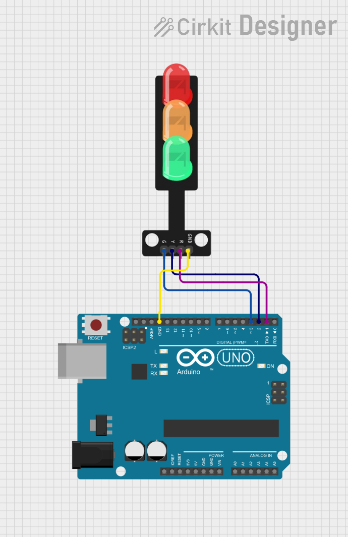
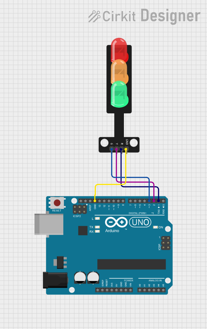
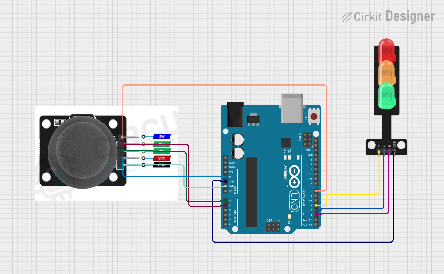
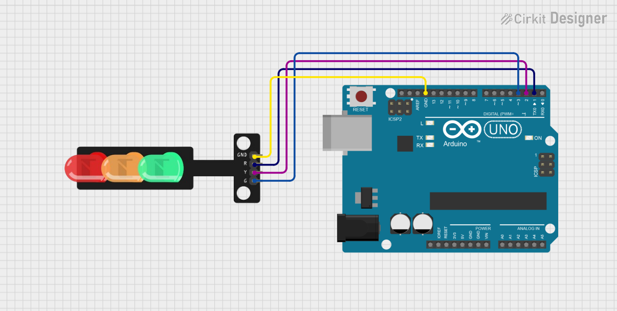
Usage Instructions

How to Use the Component in a Circuit

  1. Power Supply: Connect the VCC pin to a 5V DC power source and the GND pin to the ground.
  2. Control Pins: Use a microcontroller (e.g., Arduino UNO) or a digital circuit to control the RED, YELLOW, and GREEN pins. Set the pins HIGH to turn on the corresponding LED and LOW to turn it off.
  3. Resistors: Use appropriate current-limiting resistors (e.g., 220Ω) in series with each LED to prevent damage due to excessive current.

Important Considerations and Best Practices

  • Power Supply: Ensure a stable 5V DC power source to avoid flickering or damage to the LEDs.
  • Resistor Selection: Always use resistors to limit current through the LEDs.
  • Pin Protection: Avoid directly connecting the control pins to a high-current source to prevent damage to the LEDs or microcontroller.
  • Testing: Test each LED individually before integrating the module into a larger circuit.

Example: Connecting to an Arduino UNO

Below is an example of how to control a traffic light module using an Arduino UNO:

// Define pin numbers for the traffic light LEDs
const int redPin = 8;    // Pin connected to the red LED
const int yellowPin = 9; // Pin connected to the yellow LED
const int greenPin = 10; // Pin connected to the green LED

void setup() {
  // Set the LED pins as output
  pinMode(redPin, OUTPUT);
  pinMode(yellowPin, OUTPUT);
  pinMode(greenPin, OUTPUT);
}

void loop() {
  // Turn on the red LED and wait for 5 seconds
  digitalWrite(redPin, HIGH);
  delay(5000); // 5000ms = 5 seconds
  digitalWrite(redPin, LOW);

  // Turn on the yellow LED and wait for 2 seconds
  digitalWrite(yellowPin, HIGH);
  delay(2000); // 2000ms = 2 seconds
  digitalWrite(yellowPin, LOW);

  // Turn on the green LED and wait for 5 seconds
  digitalWrite(greenPin, HIGH);
  delay(5000); // 5000ms = 5 seconds
  digitalWrite(greenPin, LOW);
}

Notes:

  • Adjust the delay() values to simulate different traffic light timings.
  • Ensure proper connections between the Arduino and the traffic light module.

Troubleshooting and FAQs

Common Issues and Solutions

  1. LEDs Not Lighting Up:

    • Check the power supply and ensure the VCC and GND pins are correctly connected.
    • Verify that the control pins are set HIGH in the code.
    • Inspect the resistors to ensure they are not open or damaged.
  2. Flickering LEDs:

    • Ensure a stable power supply without voltage fluctuations.
    • Check for loose connections in the circuit.
  3. Incorrect LED Behavior:

    • Double-check the pin connections and ensure they match the code.
    • Verify the logic in the code to ensure the correct sequence of operations.

FAQs

Q1: Can I use a 3.3V power supply instead of 5V?
A1: Most traffic light modules are designed for 5V operation. Using 3.3V may result in dim LEDs or improper functioning. Check the module's datasheet for compatibility.

Q2: Do I need to use resistors with the module?
A2: Yes, resistors are essential to limit the current through the LEDs and prevent damage.

Q3: Can I control the traffic light module with a Raspberry Pi?
A3: Yes, you can control the module with a Raspberry Pi using its GPIO pins. Ensure you use appropriate resistors and configure the GPIO pins correctly.

Q4: How do I extend the cable length for the module?
A4: Use shielded cables to reduce noise and ensure proper connections to avoid voltage drops over long distances.

By following this documentation, you can effectively use a traffic light module in your projects and troubleshoot common issues with ease.