How to Use LF347N Op Amp: Examples, Pinouts, and Specs
Introduction
The LF347N is a quad operational amplifier (op-amp) designed for high-performance analog signal processing. It features low noise, low distortion, and high input impedance, making it ideal for applications requiring precision and reliability. The LF347N operates over a wide supply voltage range and is well-suited for audio processing, active filters, instrumentation amplifiers, and other analog circuits.
Explore Projects Built with LF347N Op Amp
Explore Projects Built with LF347N Op Amp
Common Applications
- Audio signal amplification and processing
- Active filters (low-pass, high-pass, band-pass)
- Instrumentation amplifiers
- Analog computation circuits
- Voltage followers (buffer circuits)
Technical Specifications
Key Specifications
| Parameter | Value |
|---|---|
| Supply Voltage Range | ±3V to ±18V |
| Input Offset Voltage | 5 mV (typical) |
| Input Bias Current | 50 pA (typical) |
| Input Impedance | 10⁶ MΩ (typical) |
| Output Impedance | 200 Ω (typical) |
| Slew Rate | 13 V/μs (typical) |
| Gain Bandwidth Product | 4 MHz (typical) |
| Operating Temperature Range | 0°C to +70°C |
| Package Type | DIP-14 |
Pin Configuration and Descriptions
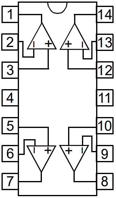
The LF347N is housed in a 14-pin Dual Inline Package (DIP-14). Below is the pinout and description:
| Pin Number | Pin Name | Description |
|---|---|---|
| 1 | Output 1 | Output of Op-Amp 1 |
| 2 | Inverting Input 1 | Inverting input of Op-Amp 1 |
| 3 | Non-Inverting Input 1 | Non-inverting input of Op-Amp 1 |
| 4 | V- (Negative Supply) | Negative power supply |
| 5 | Non-Inverting Input 2 | Non-inverting input of Op-Amp 2 |
| 6 | Inverting Input 2 | Inverting input of Op-Amp 2 |
| 7 | Output 2 | Output of Op-Amp 2 |
| 8 | Output 3 | Output of Op-Amp 3 |
| 9 | Inverting Input 3 | Inverting input of Op-Amp 3 |
| 10 | Non-Inverting Input 3 | Non-inverting input of Op-Amp 3 |
| 11 | V+ (Positive Supply) | Positive power supply |
| 12 | Non-Inverting Input 4 | Non-inverting input of Op-Amp 4 |
| 13 | Inverting Input 4 | Inverting input of Op-Amp 4 |
| 14 | Output 4 | Output of Op-Amp 4 |
Usage Instructions
Using the LF347N in a Circuit
- Power Supply: Connect the positive supply voltage (V+) to pin 11 and the negative supply voltage (V-) to pin 4. The LF347N supports a wide supply voltage range (e.g., ±12V or ±15V).
- Input Connections: Connect the input signal to the non-inverting (pins 3, 5, 10, or 12) or inverting inputs (pins 2, 6, 9, or 13) depending on the desired configuration (e.g., inverting or non-inverting amplifier).
- Output Connections: The amplified signal will be available at the corresponding output pins (pins 1, 7, 8, or 14).
- Feedback Network: Use resistors and/or capacitors in the feedback loop to set the gain and frequency response of the amplifier.
- Bypass Capacitors: Place decoupling capacitors (e.g., 0.1 µF) close to the power supply pins to reduce noise and improve stability.
Example: Non-Inverting Amplifier Circuit
Below is an example of using the LF347N as a non-inverting amplifier with an Arduino UNO to process an analog signal.
Circuit Diagram
- Connect the input signal to the non-inverting input (e.g., pin 3 for Op-Amp 1).
- Use a resistor divider network in the feedback loop to set the gain.
- Connect the output (pin 1) to an Arduino analog input pin (e.g., A0).
Arduino Code
// Example code to read the output of the LF347N non-inverting amplifier
// and display the analog value on the serial monitor.

void setup() {
  Serial.begin(9600); // Initialize serial communication at 9600 baud
}

void loop() {
  int sensorValue = analogRead(A0); // Read the analog value from pin A0
  float voltage = sensorValue * (5.0 / 1023.0); // Convert to voltage (5V reference)

  // Print the voltage to the serial monitor
  Serial.print("Voltage: ");
  Serial.print(voltage);
  Serial.println(" V");

  delay(500); // Wait for 500 ms before the next reading
}
Important Considerations
- Input Impedance: The LF347N has a high input impedance, which minimizes loading on the input signal source.
- Output Impedance: The low output impedance ensures compatibility with most loads.
- Stability: Use proper decoupling capacitors to prevent oscillations.
- Thermal Considerations: Ensure the operating temperature remains within the specified range (0°C to +70°C).
Troubleshooting and FAQs
Common Issues and Solutions
No Output Signal:
- Verify the power supply connections (V+ and V-).
- Check the input signal and ensure it is within the acceptable range.
- Confirm the feedback network is correctly configured.
Distorted Output:
- Ensure the supply voltage is adequate for the desired output swing.
- Check for proper grounding and minimize noise in the circuit.
Oscillations or Instability:
- Add decoupling capacitors (e.g., 0.1 µF) close to the power supply pins.
- Verify the feedback network and avoid excessive gain.
Overheating:
- Ensure the ambient temperature is within the operating range.
- Check for short circuits or excessive current draw.
FAQs
Q: Can the LF347N be used with a single supply voltage?
A: Yes, the LF347N can operate with a single supply voltage. However, the input signal and output range must be biased appropriately to remain within the operating range.
Q: What is the maximum gain I can achieve with the LF347N?
A: The maximum gain depends on the feedback network and the bandwidth of the op-amp. For high gains, ensure the gain-bandwidth product (4 MHz) is not exceeded.
Q: Is the LF347N suitable for audio applications?
A: Yes, the LF347N's low noise and low distortion characteristics make it an excellent choice for audio signal processing.
Q: Can I use the LF347N with an Arduino?
A: Absolutely! The LF347N can amplify analog signals for processing by an Arduino's ADC (Analog-to-Digital Converter). Ensure the output voltage is within the Arduino's input range (0-5V for most models).