Cirkit Designer
Your all-in-one circuit design IDE
Home /
Component Documentation
How to Use MCP2515: Examples, Pinouts, and Specs
Introduction
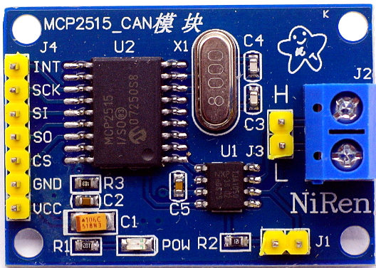
The MCP2515, manufactured by Malith (Part ID: 123), is a stand-alone Controller Area Network (CAN) controller with an SPI interface. It is designed for high-speed communication in automotive and industrial applications. The MCP2515 allows microcontrollers to communicate with CAN networks, making it an essential component in systems requiring robust and reliable data exchange.
Explore Projects Built with MCP2515
STM32 and ESP32 CAN Bus Communication System with MCP2515

This circuit integrates multiple microcontrollers (STM32F103C8T6, ESP32, and Raspberry Pi Pico W) with MCP2515 CAN controllers to facilitate CAN bus communication. The microcontrollers are connected to the MCP2515 modules via SPI interfaces, and the circuit includes USB-to-serial converters for programming and debugging purposes.
STM32F103C8T6 and MCP2515 CAN Bus Communication System with Raspberry Pi Pico and ESP32 Integration
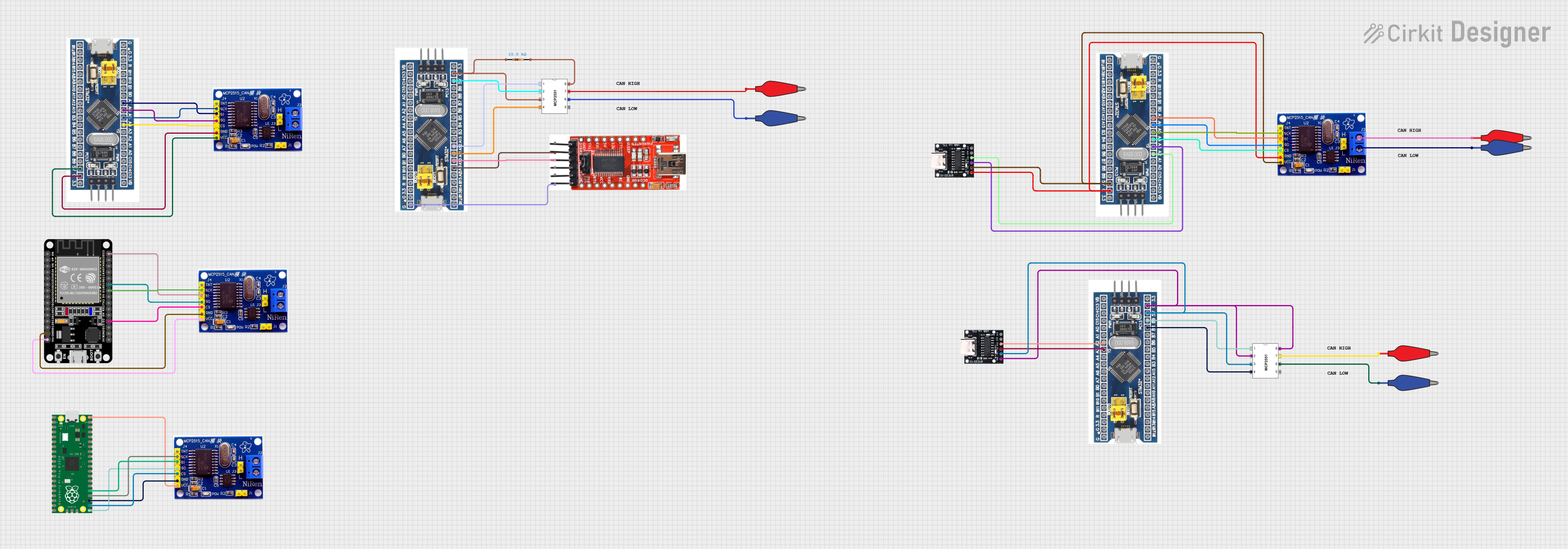
This circuit integrates multiple STM32 microcontrollers, Raspberry Pi Pico, and ESP32 with MCP2515 CAN controllers to facilitate communication over the CAN bus. The microcontrollers are connected to the MCP2515 modules via SPI interfaces, and the setup includes USB-to-serial converters for programming and debugging purposes.
ESP32 and MCP2515 CAN Bus Interface with Potentiometer Control
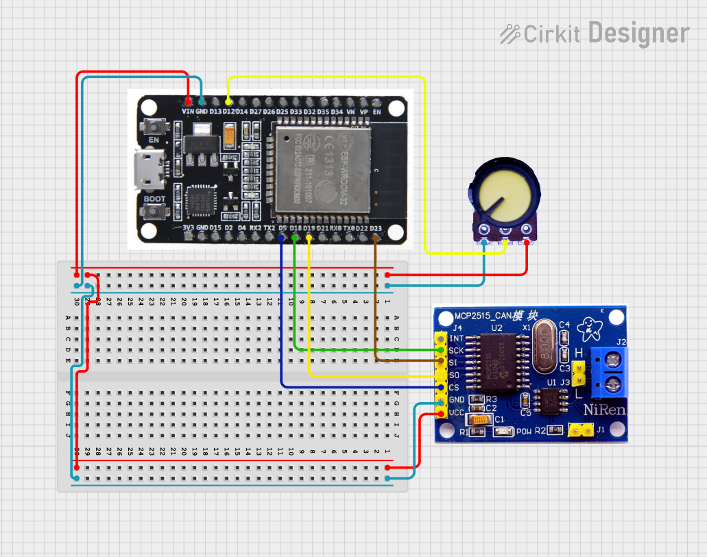
This circuit features an ESP32 microcontroller interfaced with an MCP2515 CAN controller and a potentiometer. The ESP32 reads the analog output from the potentiometer and communicates with the MCP2515 via SPI to potentially transmit or receive CAN messages.
ESP32-Based Dual CAN Bus Data Logger with Wireless Sensor Integration
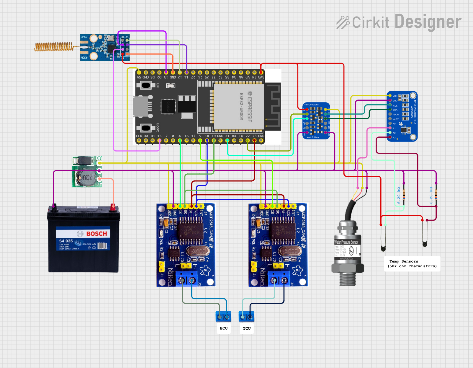
This circuit is designed to interface an ESP32 microcontroller with two CAN bus networks using MCP2515 controllers, and to collect temperature and pressure data from sensors via an ADS1015 ADC. The collected data is then transmitted wirelessly using ESP-NOW to another ESP32 connected to a display.
Explore Projects Built with MCP2515
STM32 and ESP32 CAN Bus Communication System with MCP2515
This circuit integrates multiple microcontrollers (STM32F103C8T6, ESP32, and Raspberry Pi Pico W) with MCP2515 CAN controllers to facilitate CAN bus communication. The microcontrollers are connected to the MCP2515 modules via SPI interfaces, and the circuit includes USB-to-serial converters for programming and debugging purposes.
STM32F103C8T6 and MCP2515 CAN Bus Communication System with Raspberry Pi Pico and ESP32 Integration
This circuit integrates multiple STM32 microcontrollers, Raspberry Pi Pico, and ESP32 with MCP2515 CAN controllers to facilitate communication over the CAN bus. The microcontrollers are connected to the MCP2515 modules via SPI interfaces, and the setup includes USB-to-serial converters for programming and debugging purposes.
ESP32 and MCP2515 CAN Bus Interface with Potentiometer Control
This circuit features an ESP32 microcontroller interfaced with an MCP2515 CAN controller and a potentiometer. The ESP32 reads the analog output from the potentiometer and communicates with the MCP2515 via SPI to potentially transmit or receive CAN messages.
ESP32-Based Dual CAN Bus Data Logger with Wireless Sensor Integration
This circuit is designed to interface an ESP32 microcontroller with two CAN bus networks using MCP2515 controllers, and to collect temperature and pressure data from sensors via an ADS1015 ADC. The collected data is then transmitted wirelessly using ESP-NOW to another ESP32 connected to a display.
Common Applications and Use Cases
- Automotive Systems: Engine control units, transmission control, and in-vehicle networking.
- Industrial Automation: Factory automation, robotics, and process control.
- Medical Equipment: Data acquisition and control systems.
- Consumer Electronics: Home automation and smart appliances.
Technical Specifications
Key Technical Details
| Parameter | Value |
|---|---|
| Operating Voltage | 2.7V to 5.5V |
| Operating Current | 10 mA (typical) |
| CAN Interface | High-speed (up to 1 Mbps) |
| SPI Interface | Up to 10 MHz |
| Temperature Range | -40°C to +125°C |
| Package Types | SOIC, PDIP, TSSOP |
Pin Configuration and Descriptions
| Pin No. | Pin Name | Description |
|---|---|---|
| 1 | VSS | Ground |
| 2 | VDD | Supply Voltage |
| 3 | CS | Chip Select (Active Low) |
| 4 | SO | SPI Data Output |
| 5 | SI | SPI Data Input |
| 6 | SCK | SPI Clock Input |
| 7 | INT | Interrupt Output (Active Low) |
| 8 | RX0BF | Receive Buffer 0 Full Interrupt Output (Active Low) |
| 9 | RX1BF | Receive Buffer 1 Full Interrupt Output (Active Low) |
| 10 | TX0RTS | Transmit Buffer 0 Request to Send (Active Low) |
| 11 | TX1RTS | Transmit Buffer 1 Request to Send (Active Low) |
| 12 | TX2RTS | Transmit Buffer 2 Request to Send (Active Low) |
| 13 | CLKOUT | Clock Output |
| 14 | OSC1 | Oscillator Input |
| 15 | OSC2 | Oscillator Output |
| 16 | RESET | Reset (Active Low) |
Usage Instructions
How to Use the MCP2515 in a Circuit
- Power Supply: Connect the VDD pin to a 3.3V or 5V power supply and the VSS pin to ground.
- SPI Interface: Connect the SPI pins (CS, SO, SI, SCK) to the corresponding pins on the microcontroller.
- CAN Bus: Connect the CANH and CANL pins to the CAN bus lines.
- Oscillator: Connect an external crystal oscillator to the OSC1 and OSC2 pins.
- Interrupts: Optionally, connect the INT pin to a microcontroller interrupt pin for handling CAN interrupts.
Important Considerations and Best Practices
- Decoupling Capacitors: Place decoupling capacitors (0.1µF and 10µF) close to the VDD pin to filter out noise.
- Termination Resistors: Use 120-ohm termination resistors at both ends of the CAN bus to ensure signal integrity.
- PCB Layout: Keep the CANH and CANL traces as short and direct as possible to minimize noise and signal degradation.
- Software Initialization: Properly initialize the MCP2515 in your software to configure the CAN bus speed, filters, and masks.
Example Code for Arduino UNO
#include <SPI.h>
#include <mcp2515.h>

struct can_frame canMsg;
MCP2515 mcp2515(10); // CS pin is connected to pin 10

void setup() {
  Serial.begin(115200);
  SPI.begin();
  mcp2515.reset();
  mcp2515.setBitrate(CAN_500KBPS, MCP_8MHZ); // Set CAN speed to 500kbps
  mcp2515.setNormalMode();

  canMsg.can_id  = 0x036; // CAN ID
  canMsg.can_dlc = 2;     // Data length code
  canMsg.data[0] = 0x00;  // Data byte 1
  canMsg.data[1] = 0x01;  // Data byte 2
}

void loop() {
  mcp2515.sendMessage(&canMsg); // Send CAN message
  delay(1000); // Wait for 1 second
}
Troubleshooting and FAQs
Common Issues Users Might Face
No Communication on CAN Bus:
- Solution: Check the power supply and ensure the MCP2515 is properly powered. Verify the CAN bus connections and termination resistors.
SPI Communication Failure:
- Solution: Ensure the SPI connections (CS, SO, SI, SCK) are correct. Check the SPI clock speed and ensure it is within the MCP2515's specifications.
Interrupts Not Triggering:
- Solution: Verify the INT pin connection and ensure the microcontroller's interrupt is configured correctly.
Solutions and Tips for Troubleshooting
- Check Connections: Ensure all connections are secure and correct.
- Use a Logic Analyzer: A logic analyzer can help debug SPI communication issues.
- Verify Software Configuration: Double-check the MCP2515 initialization and configuration in your software.
- Consult the Datasheet: Refer to the MCP2515 datasheet for detailed information on registers and configuration.
By following this documentation, users should be able to effectively integrate the MCP2515 CAN controller into their projects, ensuring reliable and high-speed communication in various applications.