How to Use laser receiver: Examples, Pinouts, and Specs
Introduction
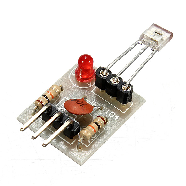
The laser receiver is a device designed to detect and convert laser light into an electrical signal. This component is widely used in various applications, including communication systems, measurement tools, and remote sensing. By converting laser light into an electrical signal, the laser receiver enables precise data transmission and accurate measurements over long distances.
Explore Projects Built with laser receiver
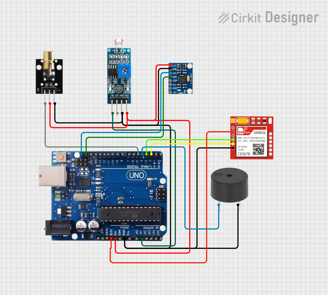
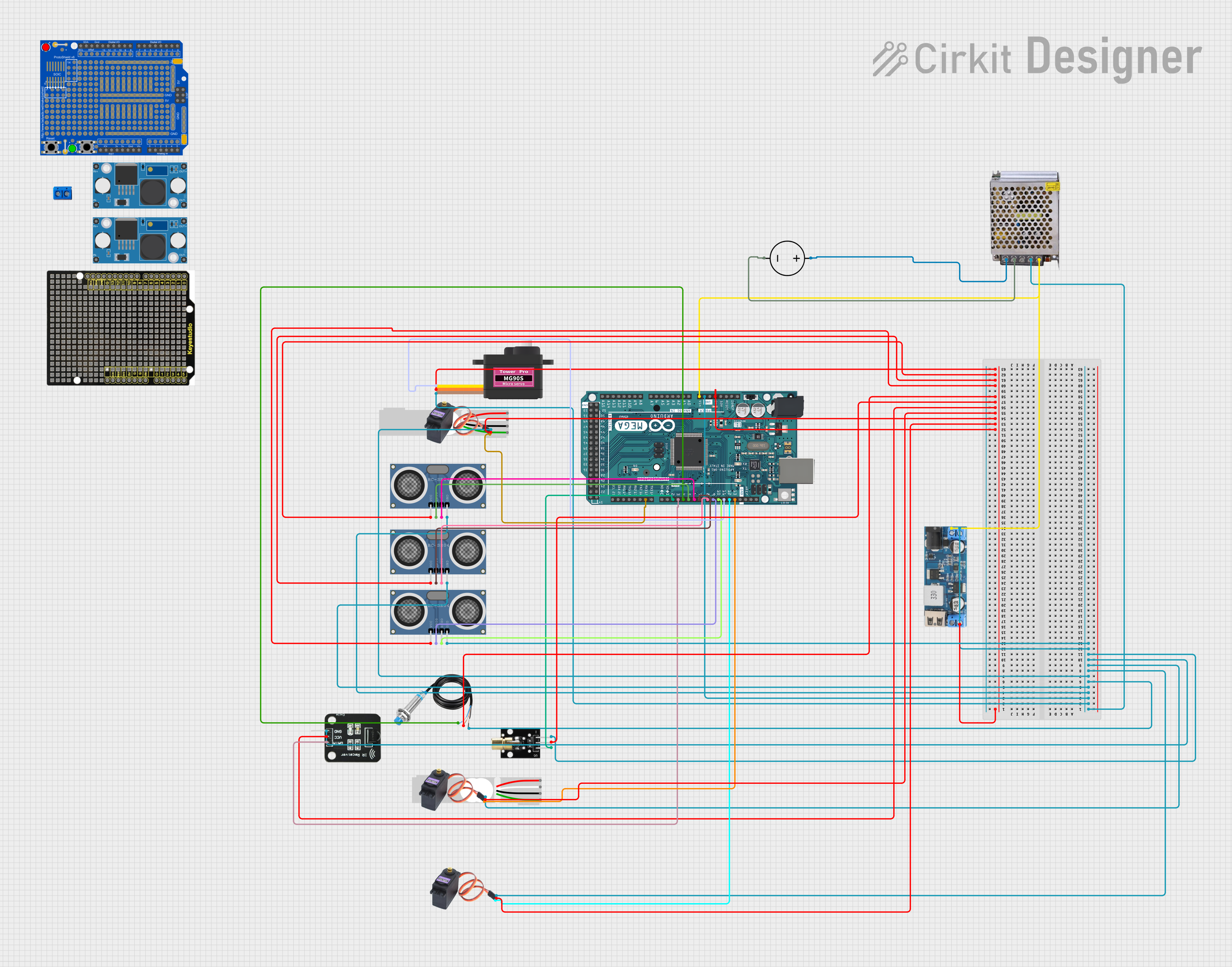
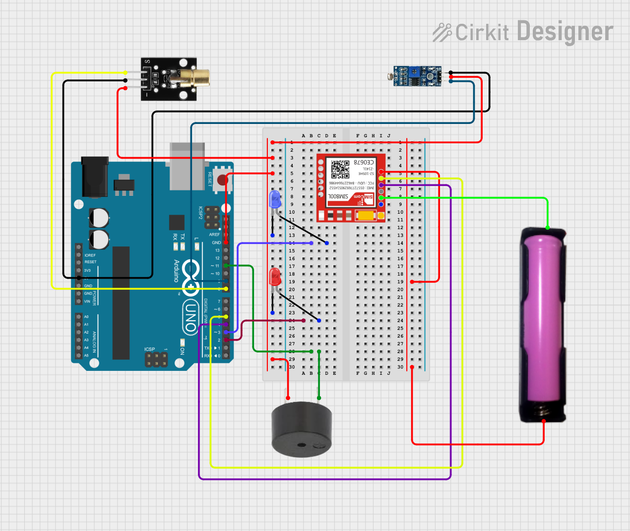
Explore Projects Built with laser receiver
Technical Specifications
Key Technical Details
| Parameter | Value |
|---|---|
| Operating Voltage | 3.3V - 5V |
| Operating Current | 10mA |
| Wavelength Range | 400nm - 1100nm |
| Sensitivity | -30dBm to -10dBm |
| Response Time | < 10ns |
| Output Type | Digital/Analog |
| Operating Temperature | -40°C to 85°C |
Pin Configuration and Descriptions
| Pin Number | Pin Name | Description |
|---|---|---|
| 1 | VCC | Power supply (3.3V - 5V) |
| 2 | GND | Ground |
| 3 | OUT | Output signal (Digital/Analog) |
| 4 | EN | Enable pin (Active High) |
Usage Instructions
How to Use the Component in a Circuit
- Power Supply: Connect the VCC pin to a 3.3V or 5V power supply and the GND pin to the ground of your circuit.
- Output Signal: Connect the OUT pin to the input of your microcontroller or any other processing unit. The output can be either digital or analog, depending on the specific model of the laser receiver.
- Enable Pin: Connect the EN pin to a digital output pin of your microcontroller. Set this pin high to enable the laser receiver.
Important Considerations and Best Practices
- Power Supply: Ensure that the power supply voltage is within the specified range (3.3V - 5V) to avoid damaging the component.
- Signal Interference: Keep the laser receiver away from strong light sources and electromagnetic interference to maintain signal integrity.
- Heat Management: If operating in high-temperature environments, consider using a heat sink or other cooling methods to prevent overheating.
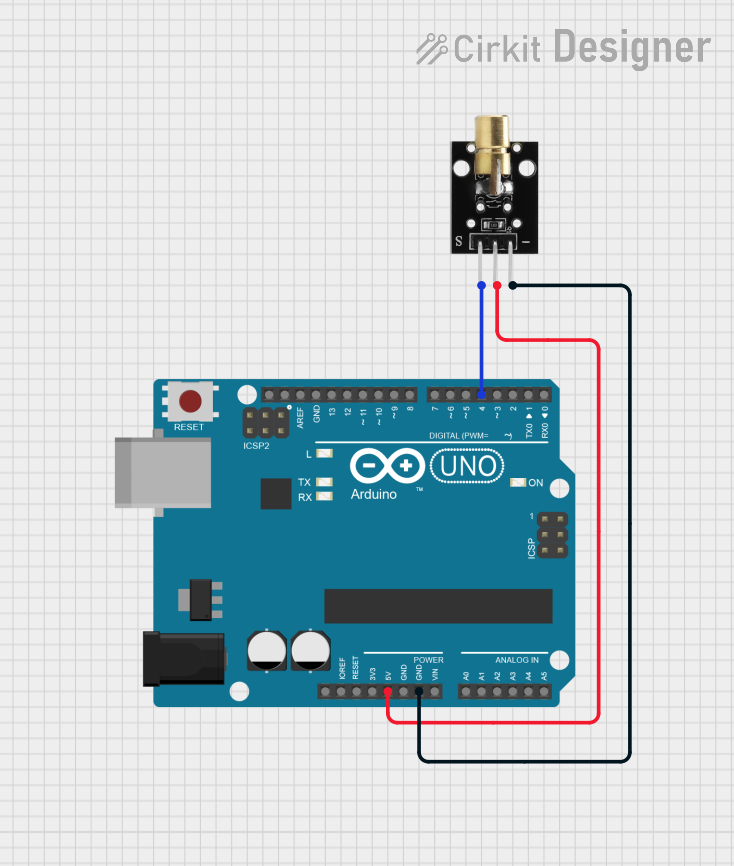
Example Circuit with Arduino UNO
// Example code to interface a laser receiver with Arduino UNO

const int laserReceiverPin = 2; // Pin connected to the OUT pin of the laser receiver
const int enablePin = 3;        // Pin connected to the EN pin of the laser receiver

void setup() {
  pinMode(laserReceiverPin, INPUT); // Set laser receiver pin as input
  pinMode(enablePin, OUTPUT);       // Set enable pin as output
  digitalWrite(enablePin, HIGH);    // Enable the laser receiver
  Serial.begin(9600);               // Initialize serial communication
}

void loop() {
  int signal = digitalRead(laserReceiverPin); // Read the signal from the laser receiver
  Serial.println(signal);                     // Print the signal value to the serial monitor
  delay(100);                                 // Wait for 100 milliseconds
}
Troubleshooting and FAQs
Common Issues Users Might Face
No Signal Detection:
- Solution: Ensure that the laser source is properly aligned with the receiver. Check the power supply and connections.
Intermittent Signal:
- Solution: Verify that there are no obstructions between the laser source and the receiver. Check for any sources of interference.
Overheating:
- Solution: Ensure that the operating temperature is within the specified range. Use cooling methods if necessary.
FAQs
Q1: Can the laser receiver detect any type of laser light?
- A1: The laser receiver is designed to detect laser light within the wavelength range of 400nm to 1100nm. Ensure that your laser source falls within this range.
Q2: How do I switch between digital and analog output?
- A2: The output type (digital or analog) depends on the specific model of the laser receiver. Refer to the datasheet of your component for detailed information.
Q3: What should I do if the signal is weak?
- A3: Check the alignment of the laser source and receiver. Ensure that there are no obstructions and that the power supply is stable.
By following this documentation, users can effectively integrate the laser receiver into their projects, ensuring reliable performance and accurate signal detection.