How to Use Voltage Regulator: Examples, Pinouts, and Specs
Introduction
A voltage regulator is an essential electronic component designed to maintain a constant voltage level. It ensures that electronic devices receive a stable power supply, which is crucial for their proper operation. Voltage regulators are widely used in various applications, including power supplies, computer systems, and battery-operated devices.
Explore Projects Built with Voltage Regulator


Explore Projects Built with Voltage Regulator
Common Applications and Use Cases
- Power supply circuits
- Battery chargers
- Automotive electronics
- Solar power systems
- Computer motherboards
- Consumer electronics
Technical Specifications
Voltage regulators come in different types, each with specific characteristics. Below are general specifications that might apply to a typical voltage regulator. For the purpose of this documentation, we will consider a linear voltage regulator with a fixed output.
Key Technical Details
- Input Voltage Range: 7V to 35V
- Output Voltage: 5V
- Output Current: 1A (max)
- Dropout Voltage: 2V
- Quiescent Current: 5mA
- Thermal Shutdown and Overcurrent Protection
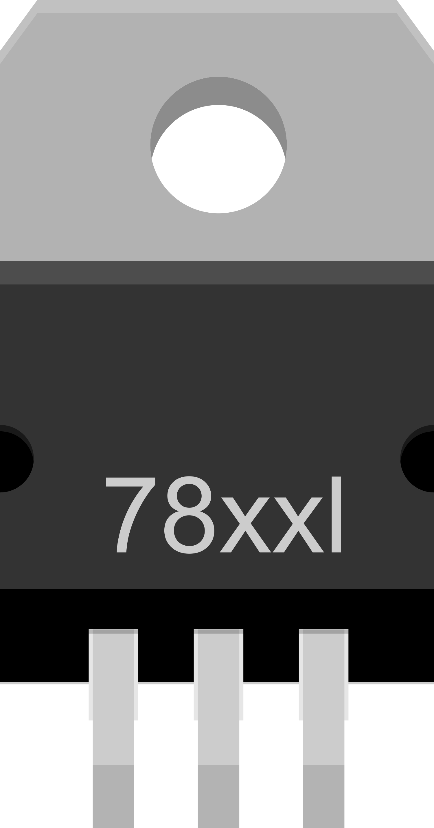
Pin Configuration and Descriptions
| Pin Number | Name | Description |
|---|---|---|
| 1 | IN | Input voltage. Connect to the unregulated supply. |
| 2 | GND | Ground reference for the regulator. |
| 3 | OUT | Regulated output voltage. |
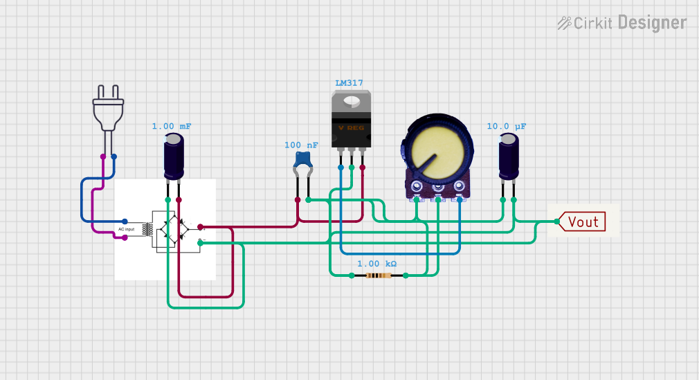
Usage Instructions
How to Use the Component in a Circuit
- Connect the input voltage to the IN pin, ensuring it is within the specified range.
- Connect the GND pin to the system ground.
- The OUT pin provides the regulated voltage; connect this to the load.
- Add a capacitor (typically 0.33µF) close to the IN pin to filter input noise.
- Add a capacitor (typically 0.1µF) close to the OUT pin to improve transient response.
Important Considerations and Best Practices
- Ensure the input voltage is always higher than the desired output voltage by at least the dropout voltage.
- Do not exceed the maximum input voltage rating to prevent damage.
- The regulator may require a heat sink to dissipate heat at higher output currents.
- Keep the input and output capacitors as close to the regulator pins as possible.
- Avoid running the regulator at its maximum rated current for extended periods to prevent thermal issues.
Troubleshooting and FAQs
Common Issues
- Output Voltage is Too Low: Check if the input voltage is above the dropout voltage. Also, verify that the load current does not exceed the maximum rating.
- Regulator Overheating: Ensure adequate heat sinking and airflow. Reduce the load current if necessary.
- Output Voltage Fluctuates: Ensure that the input and output capacitors are correctly installed and are of the recommended value.
Solutions and Tips for Troubleshooting
- If the output voltage is incorrect, recheck the input voltage and the load conditions.
- For thermal issues, consider using a regulator with a higher current rating or improve heat dissipation.
- Noise on the output can often be reduced by using larger capacitors or adding additional filtering.
FAQs
Q: Can I use a voltage regulator to step up voltage? A: No, a typical linear voltage regulator cannot step up voltage. You would need a boost converter for that purpose.
Q: What happens if I reverse the input and output pins? A: Reversing the pins can damage the regulator. Always double-check the pin orientation before powering up the circuit.
Q: How can I increase the output current capability? A: You can parallel multiple regulators with proper current sharing, but it's often better to select a regulator that can handle the required current.
Example Code for Arduino UNO
Below is an example of how to use a voltage regulator with an Arduino UNO to power the board with a higher voltage source.
// No specific code is required for the voltage regulator itself.
// The following code demonstrates a simple blink sketch
// which assumes the Arduino is powered via the voltage regulator.

void setup() {
  pinMode(LED_BUILTIN, OUTPUT); // Initialize the LED pin as an output
}

void loop() {
  digitalWrite(LED_BUILTIN, HIGH); // Turn the LED on
  delay(1000);                     // Wait for a second
  digitalWrite(LED_BUILTIN, LOW);  // Turn the LED off
  delay(1000);                     // Wait for a second
}
Note: The voltage regulator does not require code to operate. The Arduino UNO is simply powered through the regulator, and the above code is a standard blink example to demonstrate functionality.
Remember to ensure that the input voltage to the regulator is within the specified range for the Arduino UNO when using a voltage regulator to power it.