How to Use 28 PIN Connector: Examples, Pinouts, and Specs
Introduction
The 28 PIN Connector by VW is a versatile electrical connector designed to facilitate the connection of multiple wires or circuits in a compact and organized form. This connector is widely used in electronic devices, circuit boards, and automotive systems to enable efficient communication and power distribution. Its robust design ensures reliable performance in a variety of applications, making it a popular choice for engineers and hobbyists alike.
Explore Projects Built with 28 PIN Connector


Explore Projects Built with 28 PIN Connector
Common Applications and Use Cases
- Consumer Electronics: Used in devices such as televisions, gaming consoles, and audio systems.
- Automotive Systems: Facilitates connections in vehicle control units, dashboards, and lighting systems.
- Industrial Equipment: Ensures reliable connections in machinery and control panels.
- Prototyping and Development: Ideal for use in breadboards and custom PCB designs.
- IoT Devices: Provides compact and efficient connectivity for smart devices.
Technical Specifications
Key Technical Details
- Manufacturer: VW
- Number of Pins: 28
- Connector Type: Male/Female (varies by model)
- Pitch: 2.54 mm (standard spacing between pins)
- Current Rating: Up to 3A per pin
- Voltage Rating: Up to 250V
- Operating Temperature: -40°C to +105°C
- Material: High-quality thermoplastic housing with gold-plated or tin-plated contacts
- Mounting Type: Through-hole or surface-mount (varies by model)
- Durability: Rated for up to 500 mating cycles
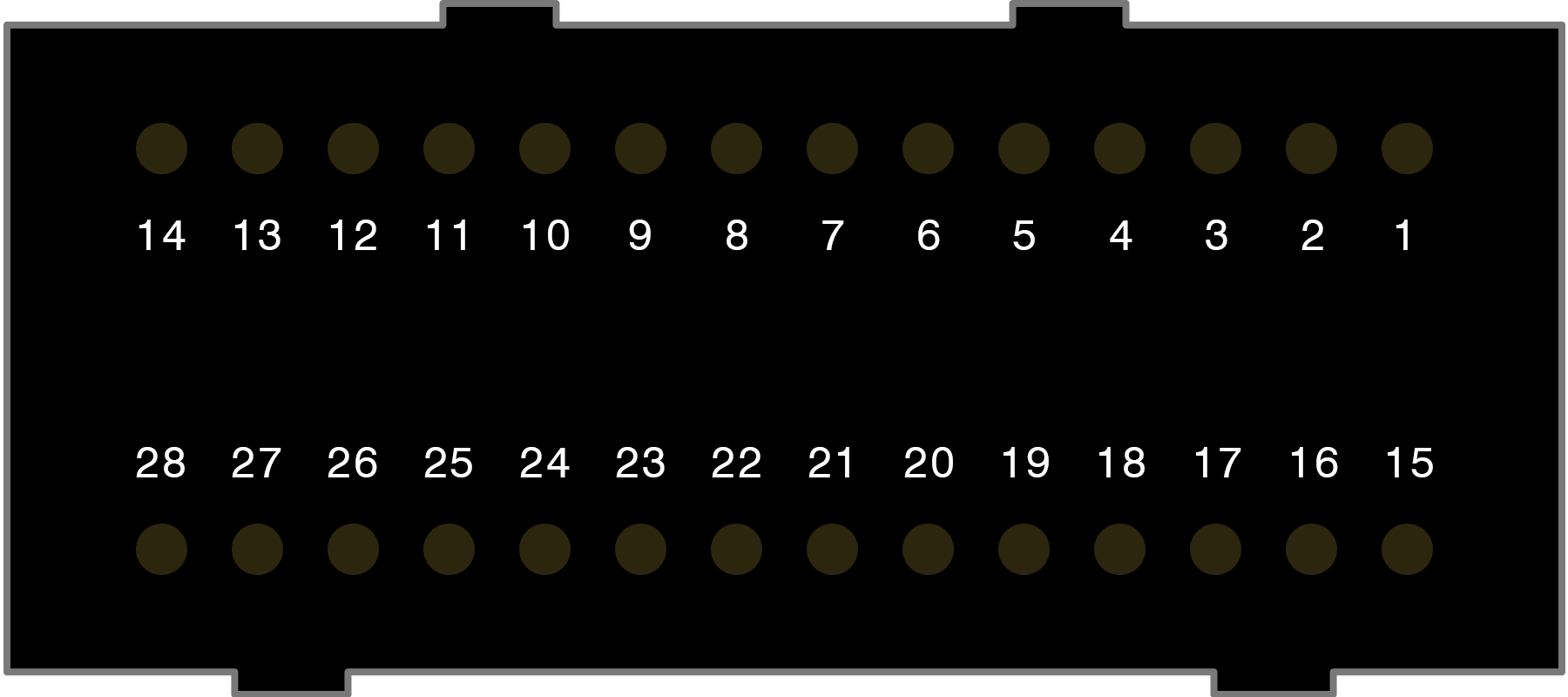
Pin Configuration and Descriptions
The 28 PIN Connector features 28 individual pins, each of which can be assigned to specific signals or power lines. Below is a general pinout description:
| Pin Number | Description | Common Use |
|---|---|---|
| 1-4 | Power Supply (VCC/GND) | Provides power to the circuit |
| 5-8 | Data Lines | Transmit and receive data |
| 9-12 | Control Signals | Enable, reset, or clock signals |
| 13-16 | Analog Inputs/Outputs | For sensors or analog devices |
| 17-20 | Communication Lines | UART, I2C, or SPI connections |
| 21-24 | GPIO | General-purpose I/O pins |
| 25-28 | Reserved/Custom Use | User-defined functionality |
Note: The exact pin configuration may vary depending on the specific application or circuit design. Always refer to the datasheet or schematic for precise details.
Usage Instructions
How to Use the 28 PIN Connector in a Circuit
- Identify Pin Functions: Refer to the pinout table or circuit schematic to determine the function of each pin.
- Soldering: If using a through-hole version, insert the connector into the PCB and solder each pin securely. For surface-mount versions, use a reflow soldering process.
- Wire Connections: Use compatible wires or ribbon cables to connect the pins to other components or devices.
- Mating: Align the male and female connectors carefully to avoid bending pins, then press them together until fully seated.
- Testing: Verify all connections using a multimeter to ensure proper continuity and functionality.
Important Considerations and Best Practices
- Avoid Overloading: Do not exceed the current or voltage ratings of the connector to prevent damage.
- Proper Alignment: Ensure the connector is properly aligned during mating to avoid pin damage.
- Secure Mounting: Use screws or clips to secure the connector in place, especially in high-vibration environments.
- Heat Management: Avoid prolonged exposure to high temperatures during soldering to prevent damage to the housing or pins.
- Cleaning: Keep the connector clean and free of debris to maintain reliable connections.
Example: Connecting to an Arduino UNO
The 28 PIN Connector can be used to interface with an Arduino UNO for prototyping. Below is an example of connecting the connector to the Arduino for a simple LED control circuit:
// Example: Controlling an LED using a 28 PIN Connector and Arduino UNO
// Pin 1: VCC (5V from Arduino)
// Pin 2: GND (Ground from Arduino)
// Pin 3: Digital Output (to LED)

const int ledPin = 3; // Pin 3 on the 28 PIN Connector is connected to an LED

void setup() {
  pinMode(ledPin, OUTPUT); // Set pin 3 as an output
}

void loop() {
  digitalWrite(ledPin, HIGH); // Turn the LED on
  delay(1000);                // Wait for 1 second
  digitalWrite(ledPin, LOW);  // Turn the LED off
  delay(1000);                // Wait for 1 second
}
Tip: Use heat-shrink tubing or cable ties to organize wires connected to the 28 PIN Connector for a cleaner setup.
Troubleshooting and FAQs
Common Issues and Solutions
Loose Connections:
- Issue: Pins are not making proper contact.
- Solution: Ensure the connector is fully seated and check for bent or damaged pins.
Overheating:
- Issue: Connector gets hot during operation.
- Solution: Verify that the current and voltage ratings are not being exceeded.
Signal Interference:
- Issue: Data signals are unreliable or noisy.
- Solution: Use shielded cables and ensure proper grounding.
Broken Pins:
- Issue: Pins are bent or broken during use.
- Solution: Replace the connector and handle it carefully during mating/demating.
FAQs
Q: Can the 28 PIN Connector handle high-speed data signals?
- A: Yes, the connector is suitable for high-speed signals, but proper shielding and grounding are recommended to minimize interference.
Q: Is the connector waterproof?
- A: Standard versions are not waterproof. For outdoor or harsh environments, use a waterproof variant.
Q: Can I use fewer than 28 pins?
- A: Yes, unused pins can be left unconnected or used for future expansion.
Q: How do I clean the connector?
- A: Use a soft brush or compressed air to remove dust and debris. Avoid using liquids unless specified by the manufacturer.
By following this documentation, users can effectively integrate the 28 PIN Connector into their projects and ensure reliable performance.