
How to Use MD10C Motor Driver: Examples, Pinouts, and Specs
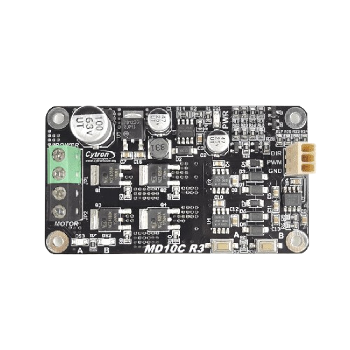
 Design with MD10C Motor Driver in Cirkit Designer
Introduction
The MD10C Motor Driver, manufactured by Cytron (Part ID: MD10C), is a robust and versatile dual-channel motor driver designed for controlling DC motors and stepper motors. It is capable of handling high current loads and offers features such as speed control and direction control. This makes it an ideal choice for robotics, automation systems, and other motor control applications.
Explore Projects Built with MD10C Motor Driver
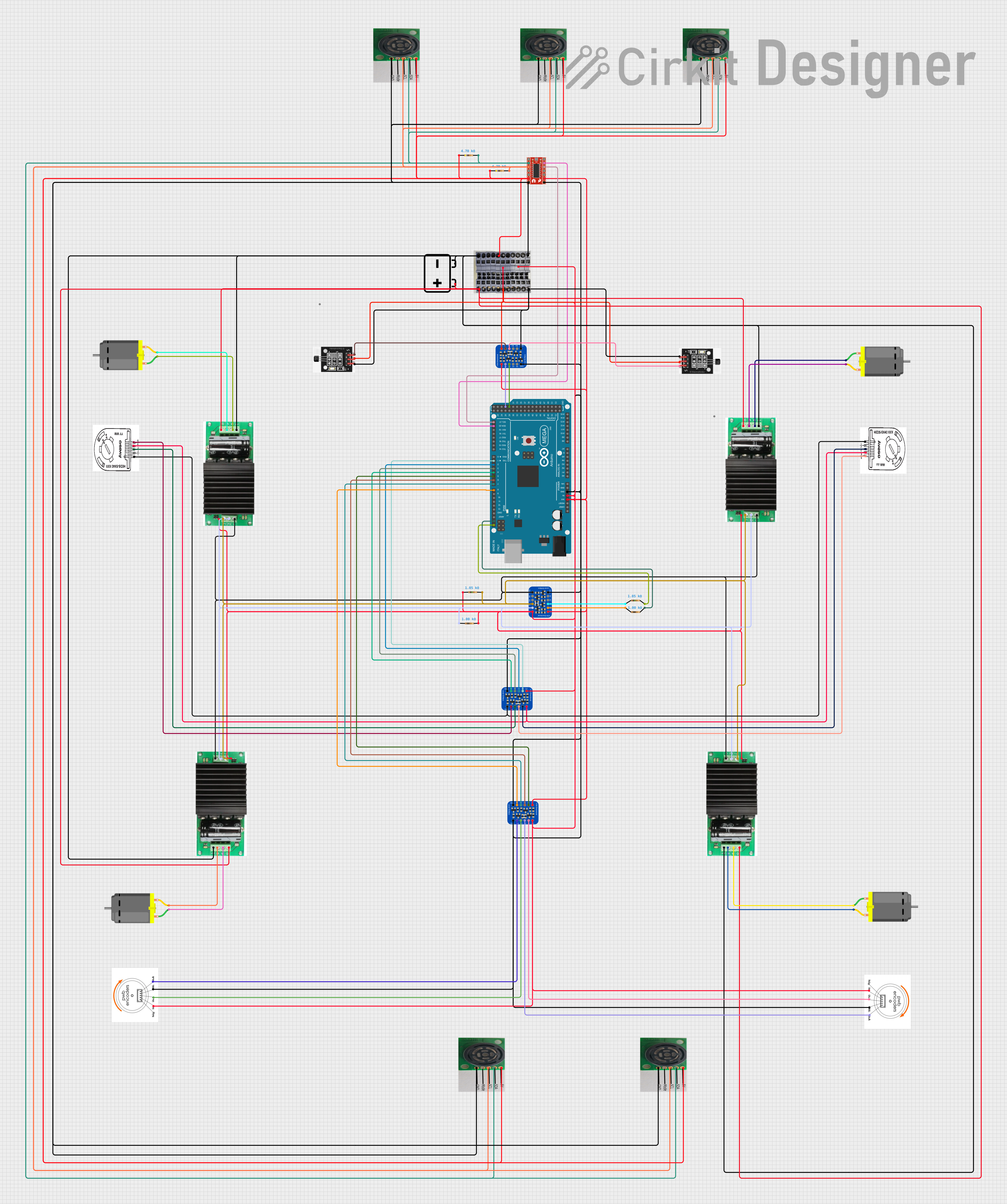 Open Project in Cirkit DesignerOpen Project in Cirkit Designer
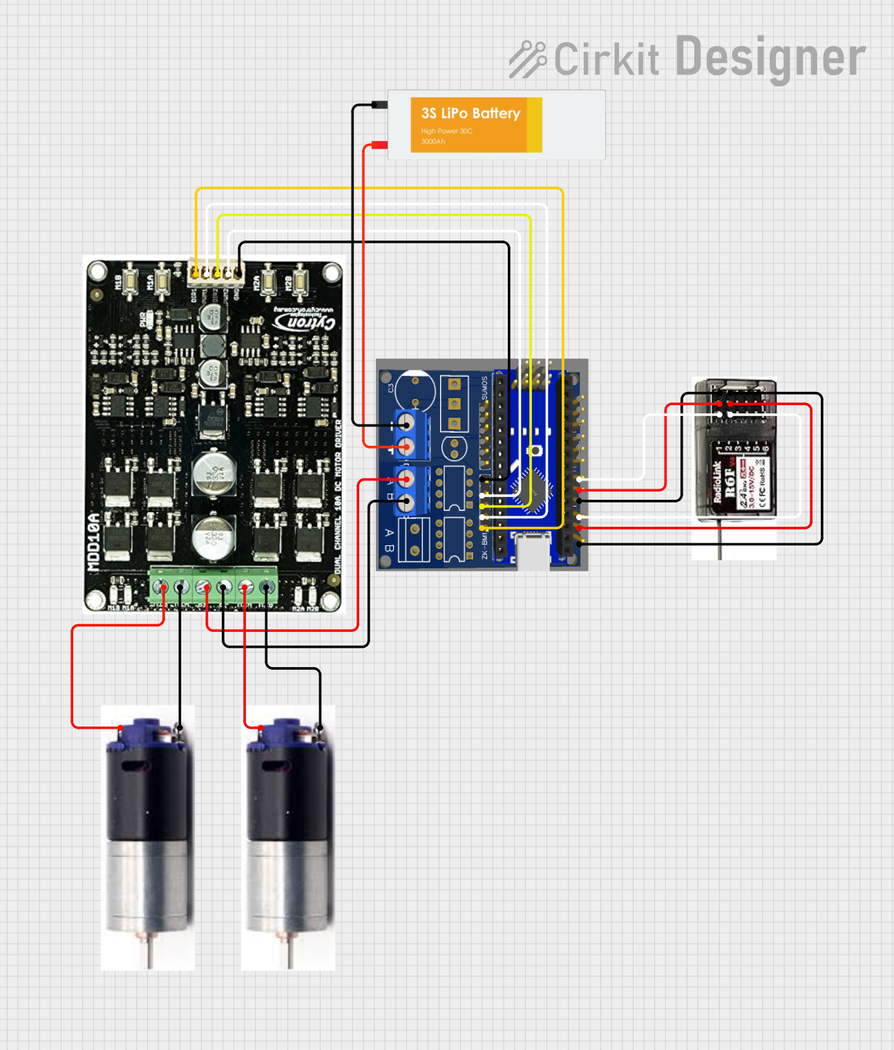 Open Project in Cirkit Designer
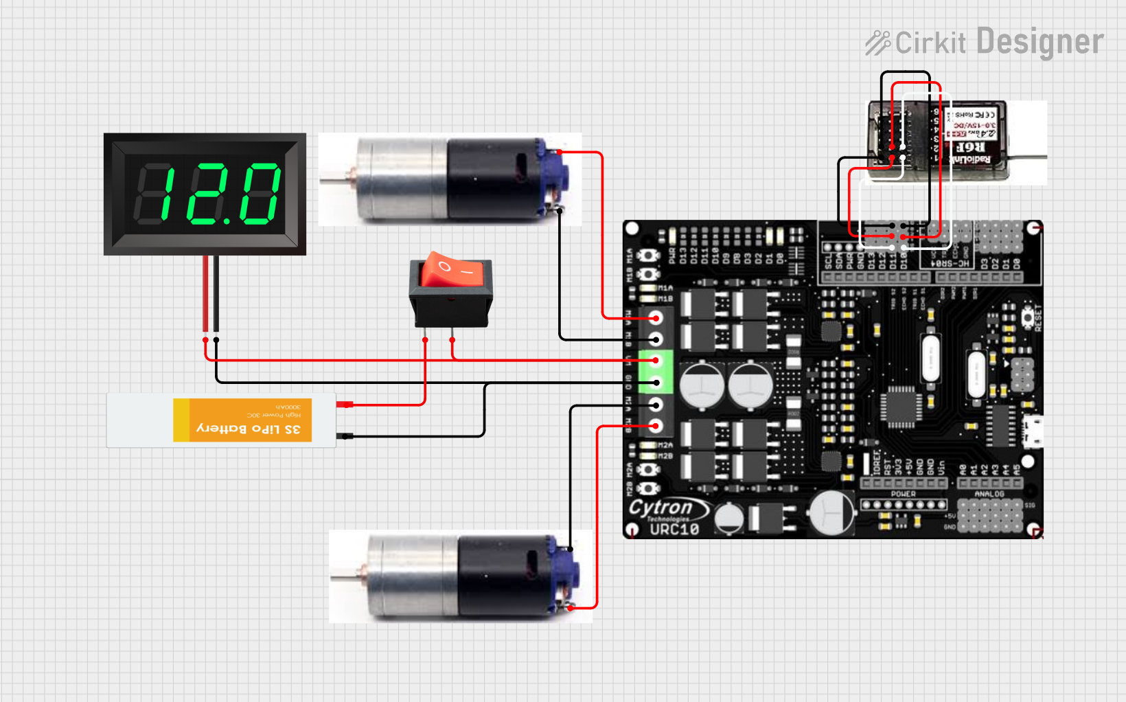 Open Project in Cirkit Designer
Explore Projects Built with MD10C Motor Driver
Open Project in Cirkit DesignerOpen Project in Cirkit DesignerOpen Project in Cirkit DesignerOpen Project in Cirkit DesignerCommon Applications
- Robotics and automation systems
- Conveyor belt systems
- Electric vehicles and carts
- Industrial motor control
- DIY projects involving DC or stepper motors
Technical Specifications
Key Specifications
| Parameter | Value |
|---|---|
| Operating Voltage | 7V to 30V |
| Continuous Current | 10A per channel |
| Peak Current | 30A (for a few seconds) |
| Control Signal Voltage | 3.3V or 5V logic compatible |
| PWM Frequency | Up to 20 kHz |
| Motor Channels | 2 |
| Protection Features | Overcurrent, Overtemperature |
| Dimensions | 84mm x 62mm x 25mm |
Pin Configuration and Descriptions
The MD10C Motor Driver has a set of input and output pins for motor control and power connections. Below is the pin configuration:
Input Pins
| Pin Name | Description |
|---|---|
| VIN | Power input for the motor driver (7V to 30V). |
| GND | Ground connection. |
| PWM1 | PWM signal input for speed control of Motor 1. |
| DIR1 | Direction control input for Motor 1. |
| PWM2 | PWM signal input for speed control of Motor 2. |
| DIR2 | Direction control input for Motor 2. |
| EN | Enable pin to activate the motor driver (active HIGH). |
Output Pins
| Pin Name | Description |
|---|---|
| M1A | Output terminal A for Motor 1. |
| M1B | Output terminal B for Motor 1. |
| M2A | Output terminal A for Motor 2. |
| M2B | Output terminal B for Motor 2. |
Usage Instructions
How to Use the MD10C Motor Driver in a Circuit
- Power Supply: Connect a DC power supply (7V to 30V) to the VIN and GND pins. Ensure the power supply can handle the current requirements of your motors.
- Motor Connections: Connect the motor terminals to the output pins (M1A, M1B for Motor 1; M2A, M2B for Motor 2).
- Control Signals:
- Connect the PWM1 and DIR1 pins to a microcontroller (e.g., Arduino) to control Motor 1.
- Similarly, connect the PWM2 and DIR2 pins to control Motor 2.
- Enable Pin: Set the EN pin HIGH to activate the motor driver.
- PWM Frequency: Use a PWM signal with a frequency of up to 20 kHz for smooth motor speed control.
Important Considerations
- Ensure the power supply voltage matches the motor's operating voltage.
- Use appropriate heat dissipation methods (e.g., heatsinks) if operating at high currents for extended periods.
- Avoid reversing the polarity of the power supply to prevent damage to the driver.
- Use logic level shifters if your microcontroller operates at 3.3V and the motor driver requires 5V signals.
Example: Using MD10C with Arduino UNO
Below is an example of how to control a single DC motor using the MD10C Motor Driver and an Arduino UNO.
// Define pin connections for Motor 1
const int pwmPin = 9;  // PWM signal for speed control
const int dirPin = 8;  // Direction control
const int enPin = 7;   // Enable pin

void setup() {
  // Set pin modes
  pinMode(pwmPin, OUTPUT);
  pinMode(dirPin, OUTPUT);
  pinMode(enPin, OUTPUT);

  // Enable the motor driver
  digitalWrite(enPin, HIGH);
}

void loop() {
  // Rotate motor in one direction
  digitalWrite(dirPin, HIGH);  // Set direction
  analogWrite(pwmPin, 128);    // Set speed (0-255)
  delay(2000);                 // Run for 2 seconds

  // Stop the motor
  analogWrite(pwmPin, 0);      // Set speed to 0
  delay(1000);                 // Wait for 1 second

  // Rotate motor in the opposite direction
  digitalWrite(dirPin, LOW);   // Change direction
  analogWrite(pwmPin, 128);    // Set speed
  delay(2000);                 // Run for 2 seconds

  // Stop the motor
  analogWrite(pwmPin, 0);      // Set speed to 0
  delay(1000);                 // Wait for 1 second
}
Notes:
- Adjust the
pwmPinvalue (0-255) to control the motor speed. - Use the
dirPinto change the motor's rotation direction.
Troubleshooting and FAQs
Common Issues and Solutions
Motor Not Running:
- Ensure the EN pin is set HIGH to enable the motor driver.
- Verify the power supply voltage and current are sufficient for the motor.
- Check the PWM and DIR signal connections to the microcontroller.
Overheating:
- Ensure proper ventilation or use a heatsink if operating at high currents.
- Reduce the motor load if possible.
Erratic Motor Behavior:
- Check for loose or faulty wiring connections.
- Verify the PWM frequency is within the supported range (up to 20 kHz).
No Response from Motor Driver:
- Confirm the polarity of the power supply is correct.
- Test the motor driver with a different motor or microcontroller to isolate the issue.
FAQs
Q: Can the MD10C control stepper motors?
A: Yes, the MD10C can control stepper motors by driving each coil as a separate motor. However, additional logic or a stepper motor controller may be required for precise step control.
Q: What happens if the current exceeds 10A?
A: The MD10C has built-in overcurrent protection. If the current exceeds the limit, the driver will shut down temporarily to protect itself.
Q: Can I use a 3.3V microcontroller with the MD10C?
A: Yes, the MD10C is compatible with both 3.3V and 5V logic levels.
Q: Is reverse polarity protection included?
A: No, the MD10C does not have reverse polarity protection. Ensure the power supply is connected correctly to avoid damage.
This concludes the documentation for the MD10C Motor Driver. For further assistance, refer to the manufacturer's datasheet or support resources.