
How to Use PIR motion sensor: Examples, Pinouts, and Specs
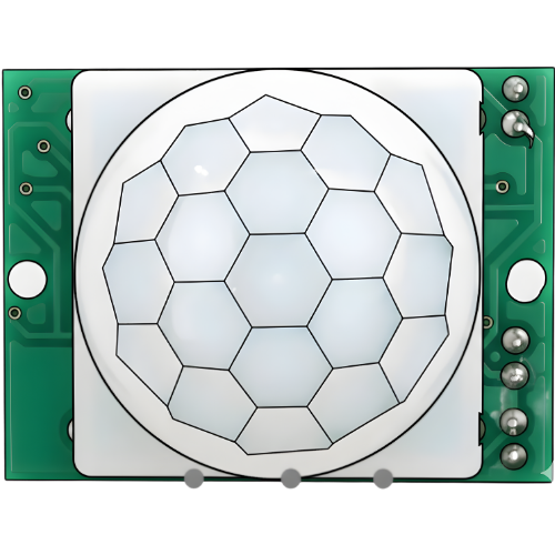
 Design with PIR motion sensor in Cirkit Designer
Introduction
A Passive Infrared (PIR) motion sensor detects motion by measuring changes in infrared radiation, typically emitted by warm bodies. It is a low-cost, low-power device widely used in motion detection applications. PIR sensors are commonly found in security systems, automatic lighting, and energy-saving devices. They are ideal for detecting human or animal movement within a specific range.
Explore Projects Built with PIR motion sensor
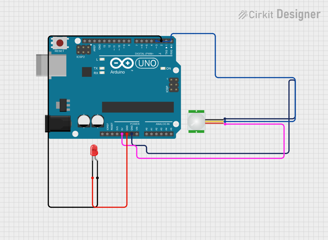 Open Project in Cirkit Designer
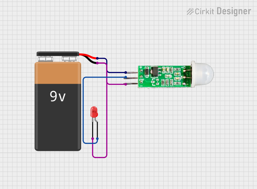 Open Project in Cirkit Designer
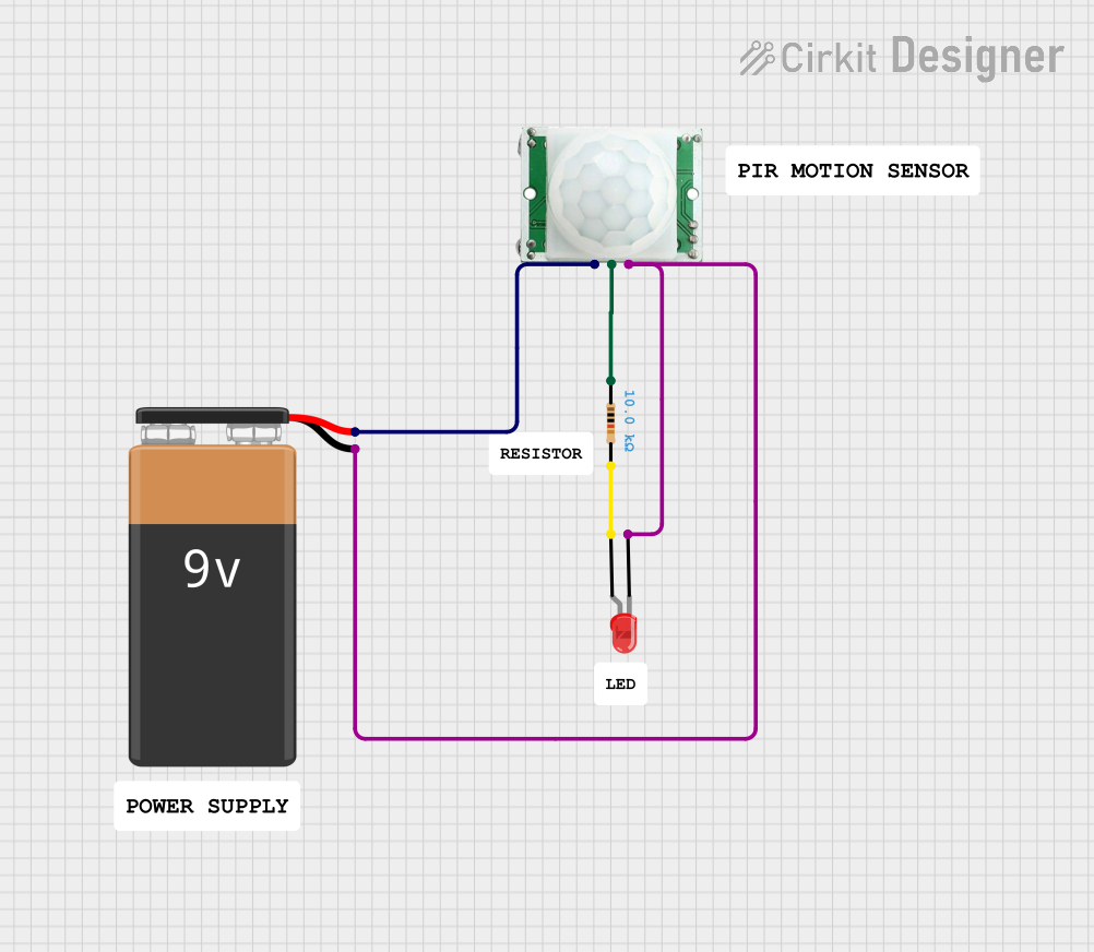 Open Project in Cirkit Designer
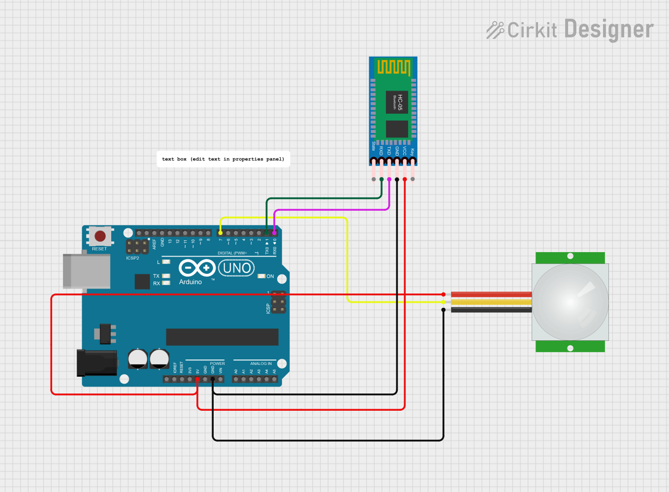 Open Project in Cirkit Designer
Explore Projects Built with PIR motion sensor
Open Project in Cirkit DesignerOpen Project in Cirkit DesignerOpen Project in Cirkit DesignerOpen Project in Cirkit DesignerTechnical Specifications
- Operating Voltage: 4.5V to 20V DC (commonly 5V or 12V)
- Current Consumption: < 60 µA
- Detection Range: 3 to 7 meters (adjustable on some models)
- Detection Angle: ~120° (varies by model)
- Output Signal: Digital (High: 3.3V or 5V, Low: 0V)
- Warm-up Time: ~30 seconds after power-up
- Trigger Modes:
- Non-retriggering (single pulse)
- Retriggering (continuous output while motion is detected)
Pin Configuration and Descriptions
| Pin Name | Description |
|---|---|
| VCC | Power supply input (4.5V to 20V DC) |
| GND | Ground connection |
| OUT | Digital output signal |
Usage Instructions
How to Use the PIR Motion Sensor in a Circuit
- Power the Sensor: Connect the VCC pin to a 5V or 12V power source and the GND pin to the ground.
- Connect the Output: Attach the OUT pin to a microcontroller's digital input pin or directly to a device (e.g., an LED or buzzer) for simple applications.
- Adjust Sensitivity and Delay (if applicable):
- Use the onboard potentiometers to adjust the detection range and the delay time for the output signal.
- Wait for Warm-up: Allow the sensor to stabilize for ~30 seconds after powering it on.
Important Considerations and Best Practices
- Avoid Direct Sunlight: PIR sensors are sensitive to infrared radiation, so avoid placing them in direct sunlight or near heat sources.
- Minimize Noise: Ensure the sensor is not exposed to electrical noise or vibrations that could cause false triggers.
- Mounting Height: Install the sensor at an appropriate height (e.g., 2-3 meters) for optimal detection.
- Trigger Modes: Configure the sensor's jumper to select between retriggering and non-retriggering modes based on your application.
Example: Connecting a PIR Sensor to an Arduino UNO
Below is an example of how to connect and use a PIR motion sensor with an Arduino UNO to control an LED.
Circuit Connections
- PIR Sensor:
- VCC → 5V on Arduino
- GND → GND on Arduino
- OUT → Digital Pin 2 on Arduino
- LED:
- Positive leg → Digital Pin 13 on Arduino (with a 220Ω resistor in series)
- Negative leg → GND on Arduino
Arduino Code
// PIR Motion Sensor with Arduino Example
// This code turns on an LED when motion is detected by the PIR sensor.

#define PIR_PIN 2       // Define the pin connected to the PIR sensor's OUT pin
#define LED_PIN 13      // Define the pin connected to the LED

void setup() {
  pinMode(PIR_PIN, INPUT);  // Set PIR sensor pin as input
  pinMode(LED_PIN, OUTPUT); // Set LED pin as output
  Serial.begin(9600);       // Initialize serial communication for debugging
}

void loop() {
  int motionDetected = digitalRead(PIR_PIN); // Read the PIR sensor output

  if (motionDetected == HIGH) { // If motion is detected
    digitalWrite(LED_PIN, HIGH); // Turn on the LED
    Serial.println("Motion detected!"); // Print message to serial monitor
  } else {
    digitalWrite(LED_PIN, LOW);  // Turn off the LED
    Serial.println("No motion."); // Print message to serial monitor
  }

  delay(100); // Small delay to stabilize readings
}
Troubleshooting and FAQs
Common Issues
False Triggers:
- Cause: Electrical noise, vibrations, or heat sources near the sensor.
- Solution: Relocate the sensor to a stable environment away from heat sources and vibrations.
No Detection:
- Cause: Incorrect wiring or insufficient power supply.
- Solution: Double-check the wiring and ensure the power supply matches the sensor's requirements.
Output Signal Stuck High/Low:
- Cause: Sensor not warmed up or faulty.
- Solution: Wait for the warm-up period (~30 seconds) or replace the sensor if it remains unresponsive.
FAQs
Q: Can the detection range be adjusted?
- A: Yes, many PIR sensors have a potentiometer to adjust the detection range.
Q: How long does the output signal stay high after motion is detected?
- A: The duration is adjustable using the delay potentiometer, typically ranging from 5 seconds to 5 minutes.
Q: Can I use a PIR sensor outdoors?
- A: Yes, but ensure it is housed in a weatherproof enclosure to protect it from moisture and extreme temperatures.
Q: What is the difference between retriggering and non-retriggering modes?
- A: In retriggering mode, the output remains high as long as motion is continuously detected. In non-retriggering mode, the output goes low after the set delay time, even if motion is still present.