How to Use Adafruit FONA 808 Breakout: Examples, Pinouts, and Specs
Introduction
The Adafruit FONA 808 Breakout is a versatile and compact module that integrates both cellular and GPS capabilities. It allows projects to connect to GSM and GPRS networks, enabling voice calls, SMS messaging, and data transmission. Additionally, with its built-in GPS module, it can provide location tracking services. This breakout is ideal for a wide range of applications, including remote monitoring, asset tracking, and IoT devices.
Explore Projects Built with Adafruit FONA 808 Breakout
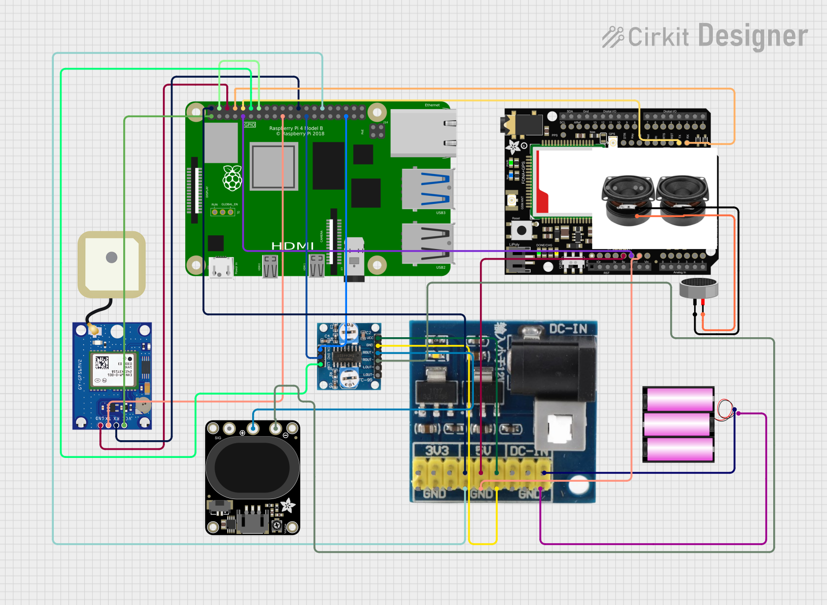

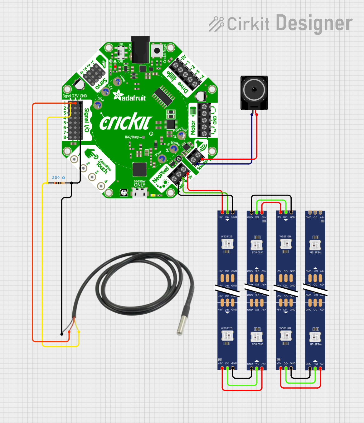

Explore Projects Built with Adafruit FONA 808 Breakout
Technical Specifications
General Features
- Network Support: Quad-band 850/900/1800/1900MHz
- GPRS Data: Class 10
- GPS: Integrated with support for NMEA sentences
- Supply Voltage: 3.4V to 4.4V recommended
- Operating Temperature: -40°C to +85°C
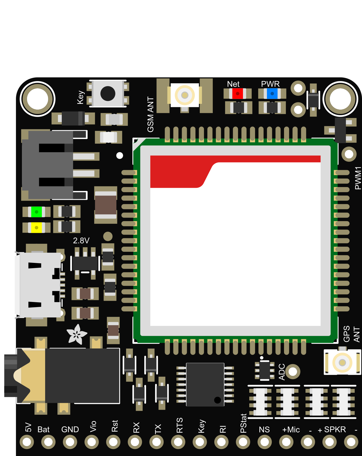
Pin Configuration and Descriptions
| Pin Number | Name | Description |
|---|---|---|
| 1 | Vio | Digital supply voltage (3.3V to 5V) |
| 2 | GND | Ground |
| 3 | RST | Reset pin (active low) |
| 4 | RX | UART receive pin |
| 5 | TX | UART transmit pin |
| 6 | Key | Power on/off control pin |
| ... | ... | ... |
| n | GPS | GPS antenna connection |
Note: This is a partial list. Refer to the full datasheet for complete pin descriptions.
Usage Instructions
Integration with a Circuit
- Power Supply: Ensure that the power supply is within the recommended voltage range. Connect Vio to a 3.3V or 5V supply, and GND to the system ground.
- UART Communication: Connect the RX and TX pins to the corresponding TX and RX pins of your microcontroller, such as an Arduino UNO.
- Antenna Connections: Attach the GSM antenna to the appropriate U.FL connector and the GPS antenna to the GPS pin.
- Powering On: To power on the FONA 808, pull the Key pin low for a brief moment.
Best Practices
- Use a stable power supply capable of delivering sufficient current for both GSM and GPS operations.
- Ensure proper antenna placement for optimal signal reception.
- Implement proper ESD precautions when handling the breakout board.
Example Code for Arduino UNO
#include <SoftwareSerial.h>

// Create software serial object to communicate with FONA
SoftwareSerial fonaSerial(2, 3); // RX, TX

void setup() {
  fonaSerial.begin(4800); // Set the baud rate for the FONA module
  Serial.begin(115200);  // Set the baud rate for the Serial monitor

  // Power on the FONA module by toggling the Key pin
  pinMode(4, OUTPUT);
  digitalWrite(4, LOW);
  delay(1000);
  digitalWrite(4, HIGH);
  delay(5000); // Wait for the module to power up

  // Check for FONA module response
  Serial.println(F("FONA basic test"));
  Serial.println(F("Initializing..."));
  fonaSerial.println("AT"); // Send AT command to check for response
  delay(1000);

  while (fonaSerial.available()) {
    Serial.write(fonaSerial.read());
  }
}

void loop() {
  // Code to interact with the FONA module can be added here
}
Note: This example demonstrates basic initialization and communication with the FONA 808. For specific functionalities like making calls, sending SMS, or using GPS, additional code is required.
Troubleshooting and FAQs
Common Issues
- Power Issues: If the module does not power on, check the power supply and Key pin connection.
- Signal Problems: Poor signal quality can affect calls and data. Ensure the antenna has a clear view of the sky.
- GPS Not Locking: If the GPS is not getting a fix, check the antenna placement and ensure it has a clear view of the sky.
Solutions and Tips
- Power Supply: Use a high-quality power supply with noise filtering.
- Antenna Placement: Keep antennas away from metal surfaces and other electronics.
- Module Reset: If the module is unresponsive, try resetting it by pulling the RST pin low.
FAQs
Q: Can I use the FONA 808 with a 5V microcontroller like the Arduino UNO? A: Yes, the FONA 808 is 5V tolerant on the UART pins, but ensure that Vio is connected to a 3.3V or 5V supply as appropriate.
Q: How do I update the firmware on the FONA 808? A: Firmware updates can be done through the UART interface using the appropriate software provided by the manufacturer.
Q: What is the power consumption of the FONA 808? A: The power consumption varies based on the mode of operation. During active calls or data transmission, it can consume more power compared to idle mode. Refer to the datasheet for detailed power consumption figures.
Note: This documentation is for informational purposes only. For detailed and specific instructions, always refer to the official datasheet and user manual provided by Adafruit.