How to Use DC Step-up Boost Converter 600W 10A CC CV: Examples, Pinouts, and Specs
Introduction
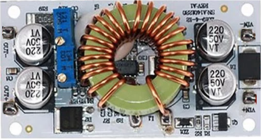
The DC Step-up Boost Converter 600W 10A CC CV is a high-performance DC-DC converter designed to increase input voltage to a higher output voltage while maintaining constant current (CC) and constant voltage (CV) regulation. This component is ideal for applications requiring efficient power delivery and precise voltage/current control.
Explore Projects Built with DC Step-up Boost Converter 600W 10A CC CV


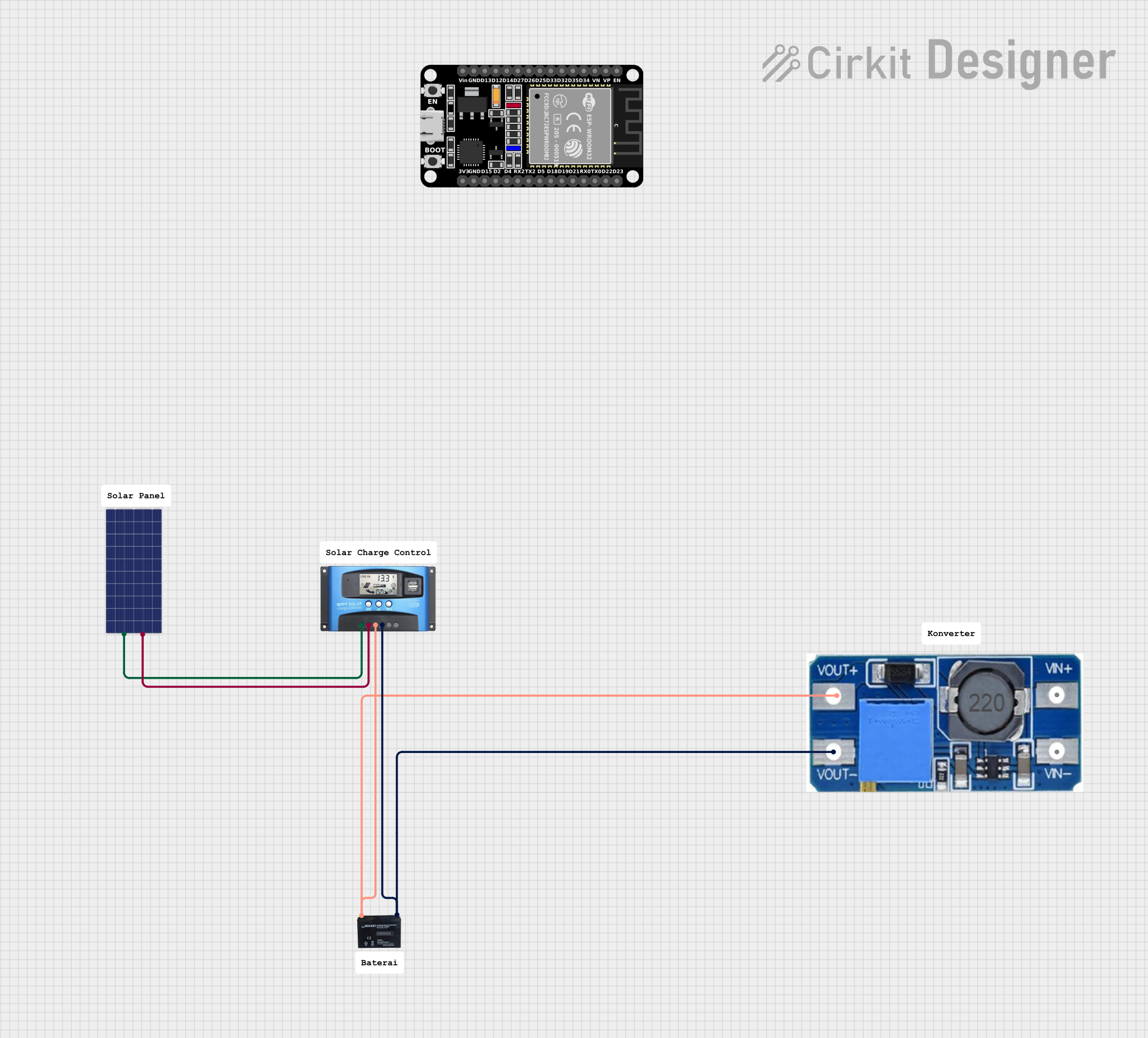
Explore Projects Built with DC Step-up Boost Converter 600W 10A CC CV
Common Applications and Use Cases
- Powering high-voltage devices from low-voltage sources (e.g., batteries, solar panels)
- DIY power supply projects
- LED drivers with adjustable brightness
- Battery charging systems
- Laboratory and testing equipment
- Electric vehicle systems
Technical Specifications
The following table outlines the key technical details of the DC Step-up Boost Converter:
| Parameter | Value |
|---|---|
| Input Voltage Range | 10V to 60V |
| Output Voltage Range | 12V to 80V |
| Output Current | Up to 10A (adjustable) |
| Output Power | Up to 600W |
| Efficiency | Up to 95% (depending on load) |
| Voltage Regulation | Constant Voltage (CV) |
| Current Regulation | Constant Current (CC) |
| Operating Temperature | -40°C to +85°C |
| Dimensions | ~130mm x 52mm x 50mm |
Pin Configuration and Descriptions
The DC Step-up Boost Converter has the following input/output terminals:
| Pin/Terminal | Description |
|---|---|
| VIN+ | Positive input voltage terminal |
| VIN- | Negative input voltage terminal (ground) |
| VOUT+ | Positive output voltage terminal |
| VOUT- | Negative output voltage terminal (ground) |
| CC Adjust | Potentiometer to adjust constant current limit |
| CV Adjust | Potentiometer to adjust constant voltage output |
Usage Instructions
How to Use the Component in a Circuit
Connect the Input Voltage:
- Connect the positive terminal of your DC power source to
VIN+. - Connect the negative terminal of your DC power source to
VIN-.
- Connect the positive terminal of your DC power source to
Connect the Load:
- Connect the positive terminal of your load to
VOUT+. - Connect the negative terminal of your load to
VOUT-.
- Connect the positive terminal of your load to
Adjust Voltage and Current:
- Use the
CV Adjustpotentiometer to set the desired output voltage. - Use the
CC Adjustpotentiometer to set the maximum output current.
- Use the
Power On:
- Turn on the input power source. The converter will step up the input voltage to the configured output voltage.
Monitor Output:
- Use a multimeter to verify the output voltage and current. Adjust the potentiometers as needed.
Important Considerations and Best Practices
- Ensure the input voltage is within the specified range (10V to 60V).
- Do not exceed the maximum output power of 600W or the maximum current of 10A.
- Use adequate heat dissipation (e.g., heatsinks or cooling fans) to prevent overheating during high-power operation.
- Always connect the load after configuring the output voltage and current to avoid damage to sensitive devices.
- For inductive loads (e.g., motors), use appropriate protection diodes to prevent back-EMF damage.
Example: Using with an Arduino UNO
The DC Step-up Boost Converter can be used to power an Arduino UNO from a low-voltage source. For example, if you have a 12V battery and need to power the Arduino at 5V:
- Set the output voltage to 5V using the
CV Adjustpotentiometer. - Connect the converter's output (
VOUT+andVOUT-) to the Arduino'sVINandGNDpins, respectively. - Ensure the current limit is set to at least 1A to handle the Arduino's power requirements.
Here is an example Arduino code to blink an LED while powered by the boost converter:
// Simple LED blink example for Arduino UNO
// Ensure the boost converter is set to 5V output before connecting to Arduino

const int ledPin = 13; // Built-in LED pin on Arduino UNO

void setup() {
  pinMode(ledPin, OUTPUT); // Set LED pin as output
}

void loop() {
  digitalWrite(ledPin, HIGH); // Turn LED on
  delay(1000);               // Wait for 1 second
  digitalWrite(ledPin, LOW);  // Turn LED off
  delay(1000);               // Wait for 1 second
}
Troubleshooting and FAQs
Common Issues and Solutions
No Output Voltage:
- Verify that the input voltage is within the specified range (10V to 60V).
- Check all connections to ensure they are secure and correctly polarized.
- Ensure the
CV Adjustpotentiometer is not set to 0V.
Overheating:
- Ensure the converter is not exceeding its maximum power rating (600W).
- Use a heatsink or cooling fan to dissipate heat during high-power operation.
Output Voltage Fluctuations:
- Verify that the input power source is stable and capable of supplying sufficient current.
- Check for loose connections or damaged wires.
Load Not Powering On:
- Ensure the output voltage and current settings are appropriate for the load.
- Check for short circuits or incorrect wiring.
FAQs
Q: Can I use this converter to charge batteries?
A: Yes, the constant current (CC) and constant voltage (CV) features make it suitable for charging batteries. Ensure the voltage and current settings match the battery's specifications.
Q: What happens if I exceed the maximum input voltage?
A: Exceeding the input voltage range (60V) can damage the converter. Always use a power source within the specified range.
Q: Can I use this converter with an inductive load like a motor?
A: Yes, but you should use protection diodes to prevent back-EMF from damaging the converter.
Q: How do I know if the converter is overheating?
A: If the converter becomes too hot to touch or shuts down unexpectedly, it may be overheating. Use additional cooling to prevent this.
By following this documentation, you can effectively use the DC Step-up Boost Converter 600W 10A CC CV in your projects while ensuring safe and reliable operation.