How to Use Mosfet IRF4905: Examples, Pinouts, and Specs
Introduction
The IRF4905 is a P-channel MOSFET designed for high-speed switching applications. It features a low on-resistance, high voltage rating, and robust thermal performance, making it ideal for use in power management circuits, motor control, and DC-DC converters. Its ability to handle high currents and voltages ensures reliable operation in demanding environments.
Explore Projects Built with Mosfet IRF4905


Explore Projects Built with Mosfet IRF4905
Common Applications:
- Power management circuits
- Motor control systems
- DC-DC converters
- Battery protection circuits
- Load switching in high-power systems
Technical Specifications
Below are the key technical details of the IRF4905 MOSFET:
| Parameter | Value |
|---|---|
| Type | P-Channel MOSFET |
| Maximum Drain-Source Voltage (VDS) | -55V |
| Maximum Gate-Source Voltage (VGS) | ±20V |
| Continuous Drain Current (ID) | -74A (at 25°C) |
| Pulsed Drain Current (IDM) | -260A |
| Power Dissipation (PD) | 200W (at 25°C) |
| On-Resistance (RDS(on)) | 0.02Ω (typical) |
| Gate Threshold Voltage (VGS(th)) | -2V to -4V |
| Operating Temperature Range | -55°C to +175°C |
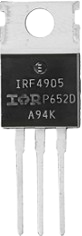
| Package Type | TO-220AB |
Pin Configuration
The IRF4905 is typically available in a TO-220AB package with three pins. The pinout is as follows:
| Pin Number | Pin Name | Description |
|---|---|---|
| 1 | Gate (G) | Controls the MOSFET switching state |
| 2 | Drain (D) | Current flows into this terminal |
| 3 | Source (S) | Current flows out of this terminal |
Usage Instructions
How to Use the IRF4905 in a Circuit
- Gate Control: Apply a voltage to the Gate (G) to control the MOSFET's switching state. For the IRF4905, the Gate voltage must be negative relative to the Source to turn it on.
- Drain-Source Current Flow: When the Gate is sufficiently negative (e.g., -10V), the MOSFET allows current to flow from the Source (S) to the Drain (D).
- Load Connection: Connect the load between the Drain (D) and the positive supply voltage. The Source (S) is connected to the ground or negative terminal of the power supply.
Important Considerations
- Gate Drive Voltage: Ensure the Gate-Source voltage (VGS) does not exceed ±20V to avoid damaging the MOSFET.
- Heat Dissipation: Use a heatsink or proper thermal management to handle the power dissipation, especially in high-current applications.
- Flyback Diode: When switching inductive loads (e.g., motors), include a flyback diode to protect the MOSFET from voltage spikes.
- Gate Resistor: Use a resistor (e.g., 10Ω) in series with the Gate to limit inrush current and prevent oscillations.
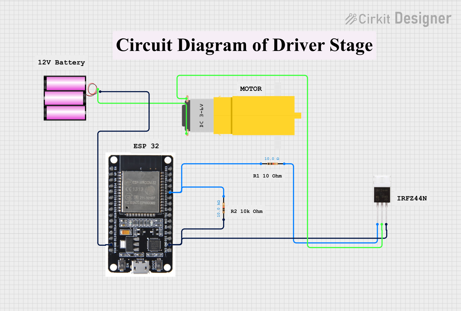
Example: Using the IRF4905 with an Arduino UNO
The IRF4905 can be controlled by an Arduino UNO to switch a load. Below is an example circuit and code:
Circuit:
- Connect the Source (S) to the ground.
- Connect the Drain (D) to one terminal of the load.
- Connect the other terminal of the load to the positive supply voltage.
- Connect the Gate (G) to a PWM-capable pin on the Arduino (e.g., pin 9) through a 10Ω resistor.
Code:
// Example code to control the IRF4905 with an Arduino UNO
// This code uses PWM to control the brightness of an LED connected to the MOSFET

const int mosfetGatePin = 9; // Pin connected to the Gate of the IRF4905

void setup() {
  pinMode(mosfetGatePin, OUTPUT); // Set the Gate pin as an output
}

void loop() {
  // Gradually increase brightness
  for (int dutyCycle = 0; dutyCycle <= 255; dutyCycle++) {
    analogWrite(mosfetGatePin, dutyCycle); // Write PWM signal to Gate
    delay(10); // Small delay for smooth transition
  }

  // Gradually decrease brightness
  for (int dutyCycle = 255; dutyCycle >= 0; dutyCycle--) {
    analogWrite(mosfetGatePin, dutyCycle); // Write PWM signal to Gate
    delay(10); // Small delay for smooth transition
  }
}
Notes:
- The Arduino's PWM output is 0-5V, which may not fully turn off the IRF4905. Use a level shifter or a driver circuit if needed.
- Ensure the load's current and voltage are within the MOSFET's ratings.
Troubleshooting and FAQs
Common Issues
MOSFET Not Switching Properly:
- Cause: Insufficient Gate-Source voltage.
- Solution: Ensure the Gate voltage is sufficiently negative (e.g., -10V) relative to the Source.
Excessive Heat:
- Cause: High current or inadequate cooling.
- Solution: Use a heatsink or improve thermal management.
MOSFET Damage:
- Cause: Exceeding voltage or current ratings.
- Solution: Verify that the circuit operates within the MOSFET's specifications.
Oscillations or Noise:
- Cause: Lack of a Gate resistor.
- Solution: Add a resistor (e.g., 10Ω) in series with the Gate.
FAQs
Q1: Can the IRF4905 be used for high-frequency switching?
A1: Yes, the IRF4905 is suitable for high-frequency switching, but ensure proper Gate drive circuitry to minimize switching losses.
Q2: Can I use the IRF4905 with a 3.3V microcontroller?
A2: No, the IRF4905 requires a negative Gate-Source voltage to turn on. Use a level shifter or a dedicated MOSFET driver.
Q3: What is the maximum load current the IRF4905 can handle?
A3: The IRF4905 can handle up to -74A continuously at 25°C, but ensure proper cooling to avoid overheating.
Q4: Do I need a flyback diode for inductive loads?
A4: Yes, a flyback diode is essential to protect the MOSFET from voltage spikes caused by inductive loads.