How to Use RTC DS13072: Examples, Pinouts, and Specs
Introduction
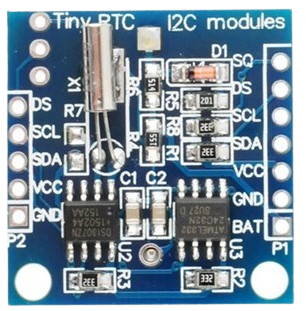
The DS1307 is a real-time clock (RTC) module manufactured by Electronics Hut, with the part ID "RTC Module." It is designed to keep track of the current time and date, including seconds, minutes, hours, day, date, month, and year. The module communicates with microcontrollers via the I2C protocol, making it easy to integrate into a wide range of projects. Additionally, the DS1307 features a battery backup, ensuring that the timekeeping functionality is maintained even during power outages.
Explore Projects Built with RTC DS13072

Explore Projects Built with RTC DS13072
Common Applications and Use Cases
- Digital clocks and timers
- Data logging systems
- Home automation projects
- Alarm systems
- Scheduling and time-based control systems
- Microcontroller-based projects requiring accurate timekeeping
Technical Specifications
The DS1307 RTC module is a versatile and reliable component. Below are its key technical details:
| Parameter | Specification |
|---|---|
| Operating Voltage | 4.5V to 5.5V |
| Backup Battery Voltage | 3.0V (typical, CR2032 coin cell) |
| Communication Protocol | I2C (Inter-Integrated Circuit) |
| I2C Address | 0x68 |
| Timekeeping Accuracy | ±2 seconds/day (at 25°C) |
| Operating Temperature | -40°C to +85°C |
| Current Consumption | 300 µA (typical, during operation) |
| Backup Mode Current | 500 nA (typical) |
| Clock Format | 12-hour or 24-hour |
| Memory | 56 bytes of non-volatile RAM |
Pin Configuration and Descriptions
The DS1307 RTC module has a simple pinout, as shown in the table below:
| Pin | Name | Description |
|---|---|---|
| 1 | GND | Ground connection |
| 2 | VCC | Power supply input (4.5V to 5.5V) |
| 3 | SDA | Serial Data Line for I2C communication |
| 4 | SCL | Serial Clock Line for I2C communication |
| 5 | BAT | Backup battery input (connect to a 3V coin cell for timekeeping during power loss) |
Usage Instructions
The DS1307 RTC module is straightforward to use in a circuit. Follow the steps below to integrate it into your project:
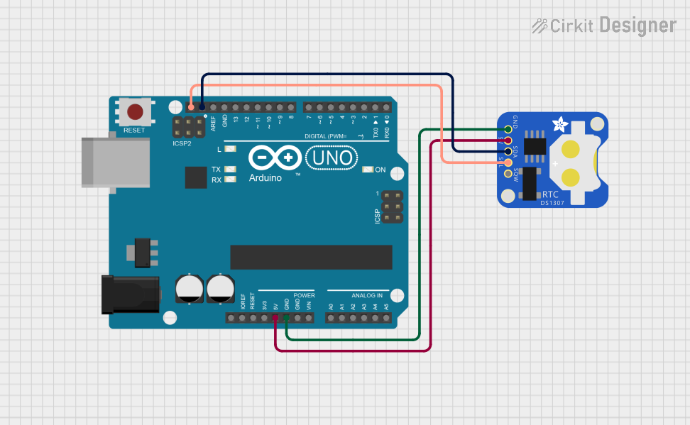
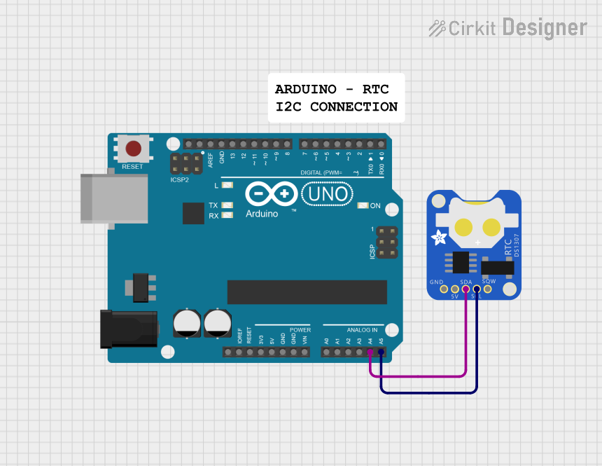
Connecting the DS1307 to a Microcontroller
- Power Supply: Connect the
VCCpin to a 5V power source and theGNDpin to ground. - I2C Communication: Connect the
SDApin to the microcontroller's I2C data line and theSCLpin to the I2C clock line. Use pull-up resistors (typically 4.7kΩ) on both lines if not already present. - Backup Battery: Insert a 3V CR2032 coin cell into the battery holder to enable timekeeping during power outages.
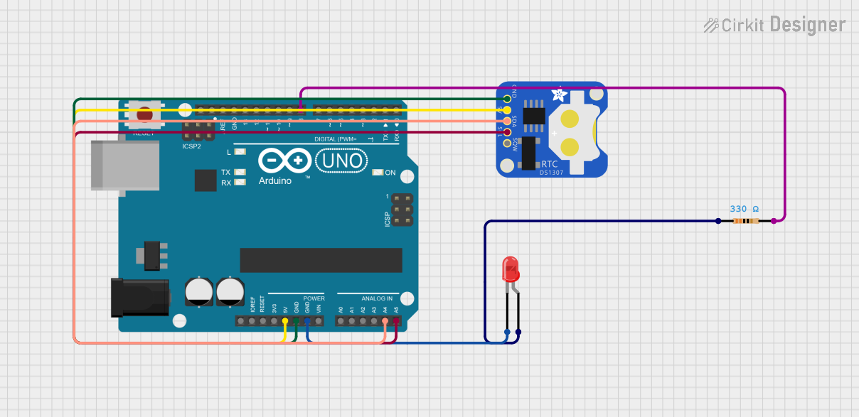
Example: Using the DS1307 with Arduino UNO
Below is an example of how to use the DS1307 RTC module with an Arduino UNO. This code uses the popular RTClib library.
Arduino Code
#include <Wire.h>
#include <RTClib.h> // Include the RTClib library for DS1307 support

RTC_DS1307 rtc; // Create an RTC object

void setup() {
  Serial.begin(9600); // Initialize serial communication at 9600 baud
  Wire.begin();       // Initialize I2C communication

  if (!rtc.begin()) {
    // Check if the RTC is connected
    Serial.println("Couldn't find RTC. Check connections!");
    while (1); // Halt the program if RTC is not found
  }

  if (!rtc.isrunning()) {
    // Check if the RTC is running
    Serial.println("RTC is NOT running! Setting the time...");
    rtc.adjust(DateTime(F(__DATE__), F(__TIME__)));
    // Set the RTC to the current date and time of the computer
  }
}

void loop() {
  DateTime now = rtc.now(); // Get the current date and time

  // Print the current date and time to the Serial Monitor
  Serial.print(now.year(), DEC);
  Serial.print('/');
  Serial.print(now.month(), DEC);
  Serial.print('/');
  Serial.print(now.day(), DEC);
  Serial.print(" ");
  Serial.print(now.hour(), DEC);
  Serial.print(':');
  Serial.print(now.minute(), DEC);
  Serial.print(':');
  Serial.print(now.second(), DEC);
  Serial.println();

  delay(1000); // Wait for 1 second before updating the time
}
Important Considerations and Best Practices
- Always use pull-up resistors on the
SDAandSCLlines if they are not already included on the module. - Ensure the backup battery is installed to maintain timekeeping during power interruptions.
- Avoid connecting the module to voltages outside its operating range (4.5V to 5.5V).
- Use decoupling capacitors near the power supply pins to reduce noise and improve stability.
Troubleshooting and FAQs
Common Issues and Solutions
RTC Not Detected by Microcontroller
- Cause: Incorrect wiring or I2C address mismatch.
- Solution: Double-check the connections and ensure the
SDAandSCLlines are properly connected. Verify that the I2C address is set to0x68.
Time Not Updating
- Cause: RTC is not running or the backup battery is missing.
- Solution: Check if the RTC is running using the
rtc.isrunning()function. Install a 3V coin cell battery if not already present.
Inaccurate Timekeeping
- Cause: Temperature variations or aging of the crystal oscillator.
- Solution: Place the module in a stable temperature environment. If the issue persists, consider recalibrating or replacing the module.
Backup Battery Drains Quickly
- Cause: Faulty battery or excessive current draw in backup mode.
- Solution: Replace the battery with a new CR2032 coin cell. Ensure no external components are drawing current from the battery.
FAQs
Q: Can the DS1307 RTC module operate without a backup battery?
A: Yes, but it will lose the current time and date when power is removed. A backup battery is recommended for uninterrupted timekeeping.
Q: What is the maximum length of the I2C bus for the DS1307?
A: The maximum length depends on the pull-up resistor values and the capacitance of the bus. Typically, it should not exceed 1 meter for reliable communication.
Q: Can the DS1307 handle daylight saving time (DST) adjustments?
A: No, the DS1307 does not have built-in support for DST. You must handle DST adjustments in your microcontroller code.
Q: Is the DS1307 compatible with 3.3V microcontrollers?
A: The DS1307 requires a 5V power supply. However, it can communicate with 3.3V microcontrollers if proper level shifting is used on the I2C lines.