
How to Use 4 Channel Relay Module: Examples, Pinouts, and Specs
 Design with 4 Channel Relay Module in Cirkit Designer
Introduction
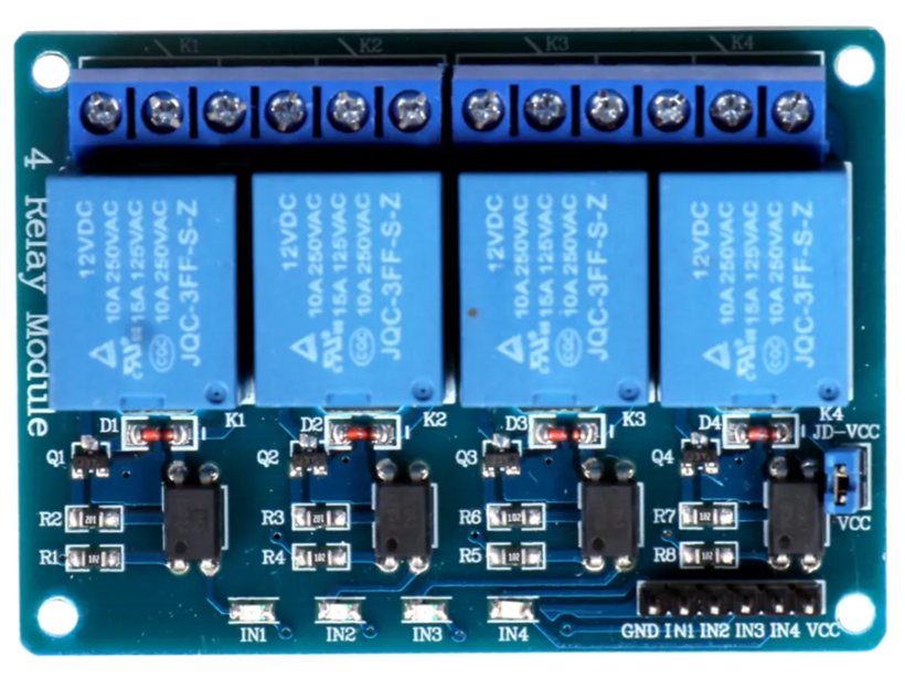
The 4 Channel Relay Module is an electronic component designed to control up to four independent circuits using low voltage signals. It acts as an interface between low-power control systems, such as microcontrollers or single-board computers, and high-power devices like lights, motors, or appliances. The module uses electromagnetic relays to safely switch high voltage or high current loads without directly exposing the control system to these potentially dangerous levels.
Explore Projects Built with 4 Channel Relay Module
 Open Project in Cirkit Designer
 Open Project in Cirkit Designer
 Open Project in Cirkit Designer
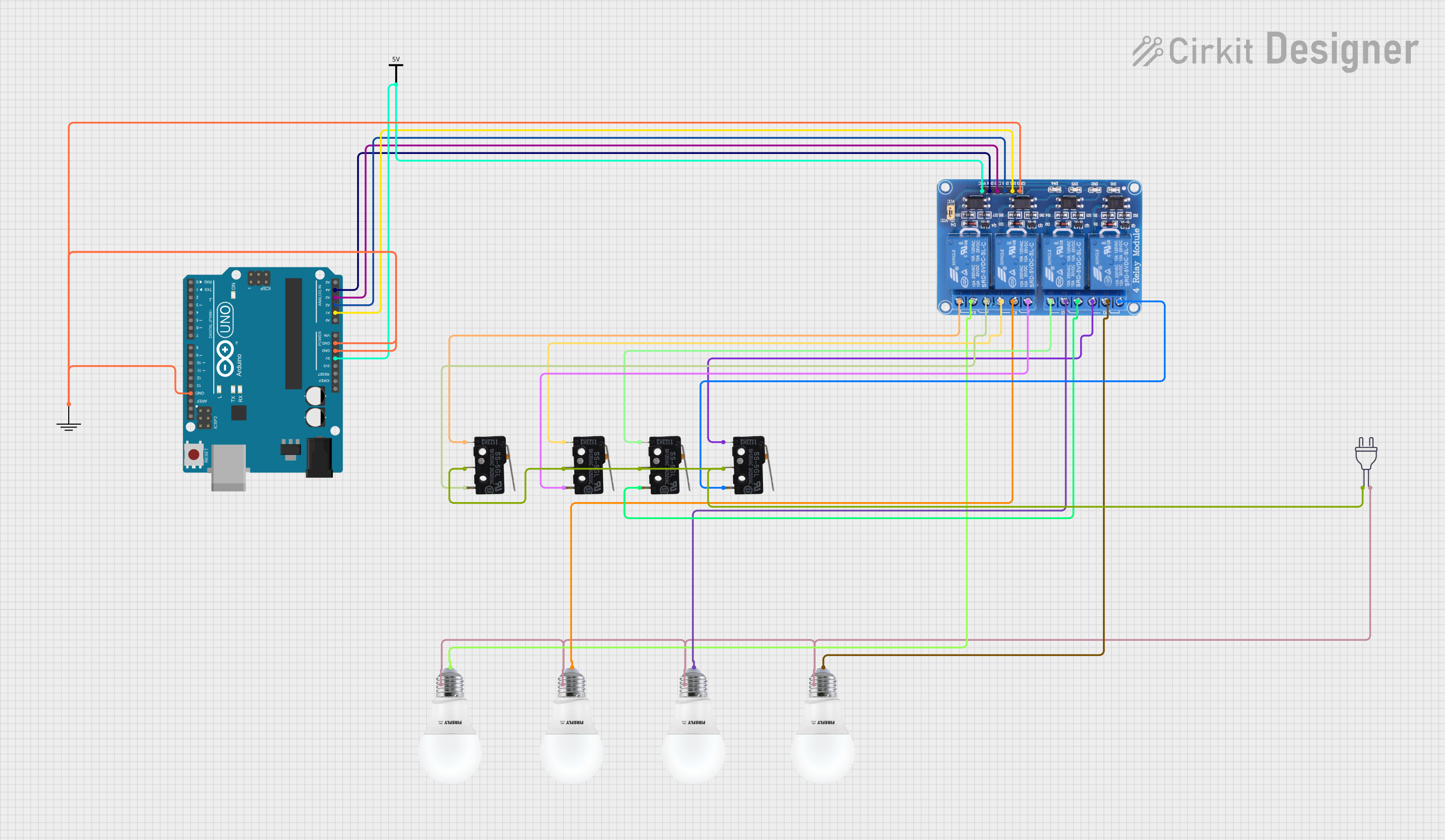 Open Project in Cirkit Designer
Explore Projects Built with 4 Channel Relay Module
Open Project in Cirkit DesignerOpen Project in Cirkit DesignerOpen Project in Cirkit DesignerOpen Project in Cirkit DesignerCommon Applications and Use Cases
- Home automation systems (e.g., controlling lights, fans, or appliances)
- Industrial automation for switching motors or solenoids
- Robotics projects requiring control of high-power actuators
- IoT (Internet of Things) applications for remote device control
- Prototyping and educational projects involving high-power switching
Technical Specifications
The 4 Channel Relay Module is designed to work with a variety of control systems and load types. Below are its key technical details:
General Specifications
- Operating Voltage: 5V DC
- Trigger Voltage: 3.3V to 5V (compatible with most microcontrollers)
- Relay Type: Electromechanical
- Maximum Load (per channel):
- AC: 250V at 10A
- DC: 30V at 10A
- Isolation: Optocoupler isolation for safe operation
- Indicator LEDs: One LED per channel to indicate relay status
- Dimensions: Approximately 75mm x 55mm x 20mm
Pin Configuration and Descriptions
The module has two main interfaces: the control pins and the relay output terminals.
Control Pins
| Pin Name | Description |
|---|---|
| VCC | Connect to the 5V power supply of the control system. |
| GND | Connect to the ground of the control system. |
| IN1 | Control signal for Relay 1 (active LOW). |
| IN2 | Control signal for Relay 2 (active LOW). |
| IN3 | Control signal for Relay 3 (active LOW). |
| IN4 | Control signal for Relay 4 (active LOW). |
Relay Output Terminals (for each channel)
| Terminal | Description |
|---|---|
| COM | Common terminal for the relay. Connect to the power source or load. |
| NO | Normally Open terminal. The circuit is open when the relay is inactive. |
| NC | Normally Closed terminal. The circuit is closed when the relay is inactive. |
Usage Instructions
How to Use the 4 Channel Relay Module in a Circuit
- Power the Module:
- Connect the VCC pin to a 5V power supply and the GND pin to the ground of your control system.
- Connect the Control Signals:
- Connect the IN1, IN2, IN3, and IN4 pins to the digital output pins of your microcontroller or control system.
- Ensure the control signals are active LOW (i.e., sending a LOW signal will activate the relay).
- Connect the Load:
- For each relay, connect the load to the COM and either the NO or NC terminal, depending on your desired behavior:
- Use NO if you want the load to be off by default and turn on when the relay is activated.
- Use NC if you want the load to be on by default and turn off when the relay is activated.
- For each relay, connect the load to the COM and either the NO or NC terminal, depending on your desired behavior:
- Test the Circuit:
- Activate the control signals to test the relays and ensure the load behaves as expected.
Important Considerations and Best Practices
- Power Supply: Ensure the module is powered by a stable 5V DC source. Avoid exceeding the voltage rating.
- Isolation: The module includes optocoupler isolation for safety, but always exercise caution when working with high voltage.
- Load Ratings: Do not exceed the maximum load ratings (250V AC/10A or 30V DC/10A) to prevent damage to the relays.
- Inductive Loads: When switching inductive loads (e.g., motors), use a flyback diode across the load to suppress voltage spikes.
- Signal Compatibility: Ensure the control signals from your microcontroller are within the 3.3V to 5V range.
Example: Connecting to an Arduino UNO
Below is an example of how to control the 4 Channel Relay Module using an Arduino UNO:
Circuit Connections
- Connect the module's VCC to the Arduino's 5V pin and GND to the Arduino's GND pin.
- Connect IN1, IN2, IN3, and IN4 to Arduino digital pins 7, 6, 5, and 4, respectively.
- Connect a load (e.g., a light bulb) to one of the relay channels.
Arduino Code
// Define the relay control pins
#define RELAY1 7  // Relay 1 connected to pin 7
#define RELAY2 6  // Relay 2 connected to pin 6
#define RELAY3 5  // Relay 3 connected to pin 5
#define RELAY4 4  // Relay 4 connected to pin 4

void setup() {
  // Set relay pins as outputs
  pinMode(RELAY1, OUTPUT);
  pinMode(RELAY2, OUTPUT);
  pinMode(RELAY3, OUTPUT);
  pinMode(RELAY4, OUTPUT);

  // Initialize all relays to OFF (HIGH state for active LOW logic)
  digitalWrite(RELAY1, HIGH);
  digitalWrite(RELAY2, HIGH);
  digitalWrite(RELAY3, HIGH);
  digitalWrite(RELAY4, HIGH);
}

void loop() {
  // Example: Turn relays on and off sequentially
  digitalWrite(RELAY1, LOW);  // Turn on Relay 1
  delay(1000);                // Wait for 1 second
  digitalWrite(RELAY1, HIGH); // Turn off Relay 1

  digitalWrite(RELAY2, LOW);  // Turn on Relay 2
  delay(1000);                // Wait for 1 second
  digitalWrite(RELAY2, HIGH); // Turn off Relay 2

  digitalWrite(RELAY3, LOW);  // Turn on Relay 3
  delay(1000);                // Wait for 1 second
  digitalWrite(RELAY3, HIGH); // Turn off Relay 3

  digitalWrite(RELAY4, LOW);  // Turn on Relay 4
  delay(1000);                // Wait for 1 second
  digitalWrite(RELAY4, HIGH); // Turn off Relay 4
}
Troubleshooting and FAQs
Common Issues and Solutions
Relays Not Activating:
- Ensure the module is powered with a stable 5V supply.
- Verify that the control signals are active LOW (i.e., sending a LOW signal activates the relay).
- Check the connections between the control system and the module.
Load Not Switching:
- Confirm that the load is properly connected to the relay terminals (COM, NO, or NC).
- Verify that the load does not exceed the relay's maximum ratings.
Indicator LEDs Not Lighting Up:
- Check the power supply to the module.
- Ensure the control signals are correctly connected and functioning.
Noise or Chattering Relays:
- Use a decoupling capacitor (e.g., 100µF) across the module's power supply to stabilize voltage.
- Avoid long wires for control signals to reduce interference.
FAQs
Q: Can I use the module with a 3.3V microcontroller like the ESP32?
A: Yes, the module is compatible with 3.3V control signals, but ensure the power supply to the module is 5V.
Q: Is it safe to use the module with high voltage AC loads?
A: Yes, but always follow proper safety precautions when working with high voltage. Ensure the load does not exceed the relay's maximum ratings.
Q: Can I control all four relays simultaneously?
A: Yes, you can activate all four relays at the same time, provided your power supply can handle the current draw.
Q: What is the purpose of the optocouplers?
A: Optocouplers provide electrical isolation between the control system and the high-power circuits, enhancing safety and protecting the control system from voltage spikes.