How to Use RDA5807FP: Examples, Pinouts, and Specs
Introduction
The RDA5807FP is a highly integrated FM radio receiver chip manufactured by RDA Microelectronics. It is designed for portable applications and offers excellent performance with low power consumption. The chip supports a wide range of FM frequencies and includes an integrated audio Digital-to-Analog Converter (DAC) for high-quality audio output. Additionally, the RDA5807FP features an I2C interface, making it easy to integrate with microcontrollers and other digital systems.
Explore Projects Built with RDA5807FP


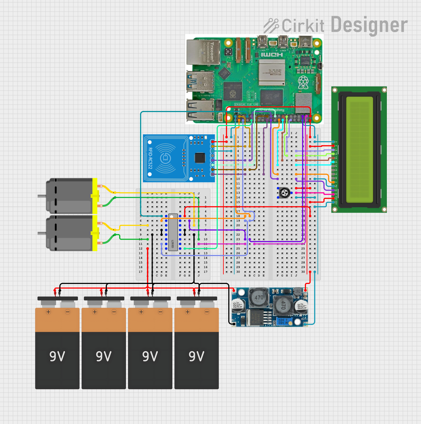
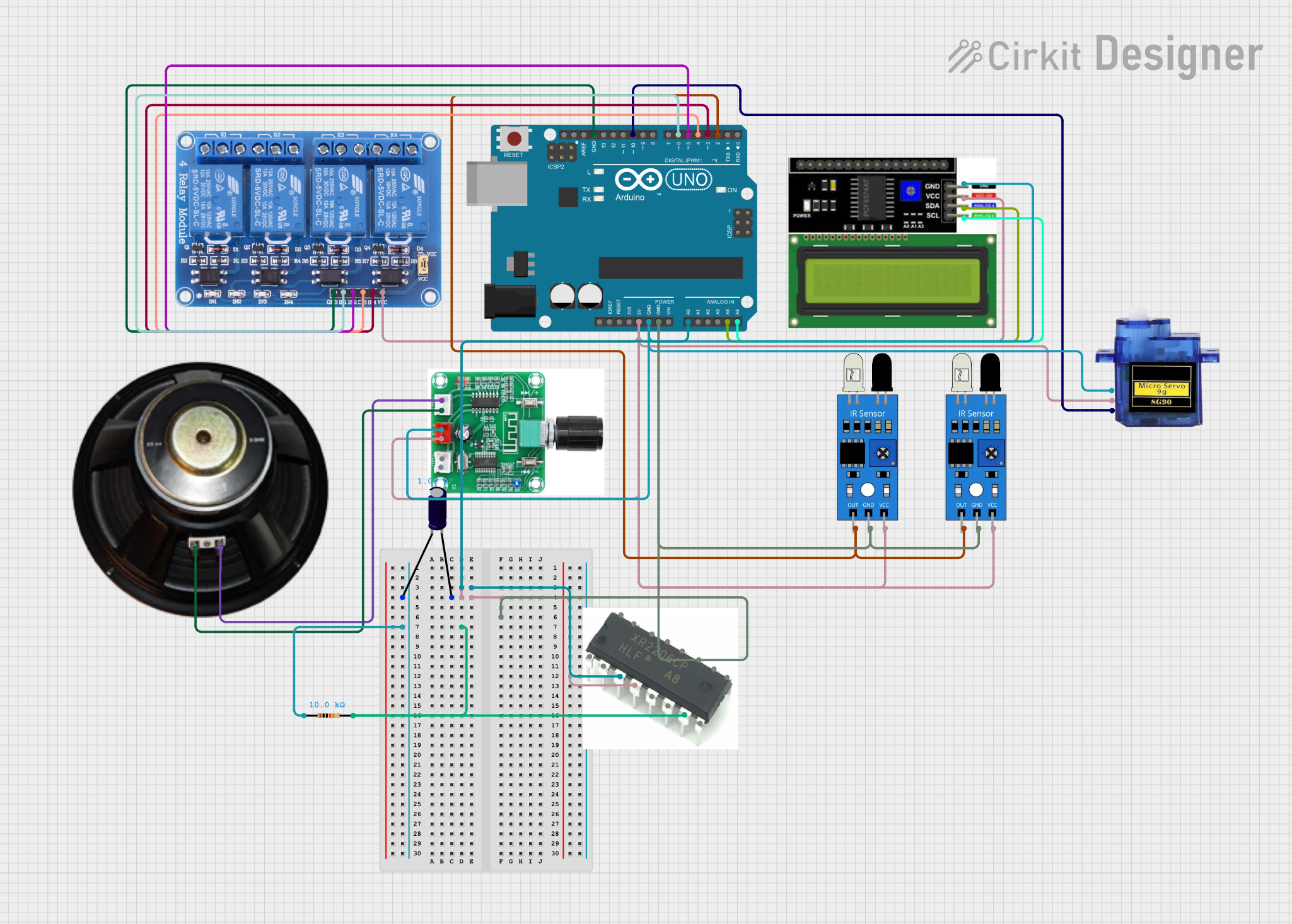
Explore Projects Built with RDA5807FP
Common Applications and Use Cases
- Portable FM radios
- MP3 players with FM functionality
- Wireless audio systems
- Embedded systems requiring FM radio reception
- Battery-operated devices
Technical Specifications
The following table outlines the key technical details of the RDA5807FP:
| Parameter | Value |
|---|---|
| Operating Voltage | 2.7V to 3.6V |
| Supply Current | 15 mA (typical) |
| Frequency Range | 50 MHz to 115 MHz |
| Audio Output | Integrated stereo DAC |
| Communication Interface | I2C |
| Sensitivity | -107 dBm |
| Signal-to-Noise Ratio | 60 dB (typical) |
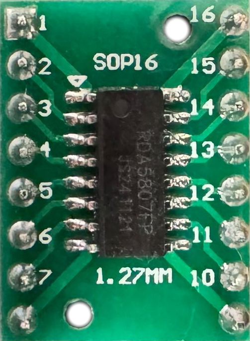
| Package Type | SOP16 |
Pin Configuration and Descriptions
The RDA5807FP comes in a 16-pin SOP package. The pin configuration and descriptions are as follows:
| Pin Number | Pin Name | Description |
|---|---|---|
| 1 | SDA | I2C data line |
| 2 | SCL | I2C clock line |
| 3 | GND | Ground |
| 4 | VDD | Power supply (2.7V to 3.6V) |
| 5 | LOUT | Left audio output |
| 6 | ROUT | Right audio output |
| 7 | NC | Not connected |
| 8 | NC | Not connected |
| 9 | NC | Not connected |
| 10 | NC | Not connected |
| 11 | NC | Not connected |
| 12 | NC | Not connected |
| 13 | NC | Not connected |
| 14 | NC | Not connected |
| 15 | NC | Not connected |
| 16 | NC | Not connected |
Note: Pins labeled as "NC" are not connected internally and should be left unconnected in the circuit.
Usage Instructions
How to Use the RDA5807FP in a Circuit
- Power Supply: Connect the VDD pin to a stable power source within the range of 2.7V to 3.6V. Connect the GND pin to the ground of the circuit.
- I2C Communication: Use the SDA and SCL pins to interface with a microcontroller or other I2C master device. Pull-up resistors (typically 4.7 kΩ) are required on these lines.
- Audio Output: Connect the LOUT and ROUT pins to an audio amplifier or directly to headphones for stereo audio output.
- Antenna: Attach an external antenna to improve FM signal reception. The antenna can be a simple wire or a more sophisticated design, depending on the application.
Important Considerations and Best Practices
- Decoupling Capacitors: Place a 0.1 µF ceramic capacitor close to the VDD pin to filter out power supply noise.
- I2C Address: The default I2C address of the RDA5807FP is
0x10. Ensure that no other devices on the I2C bus share this address. - Audio Filtering: Use appropriate capacitors on the audio output lines to filter out high-frequency noise.
- Antenna Design: For optimal performance, use an antenna tuned to the FM frequency range (88 MHz to 108 MHz for most regions).
Example Code for Arduino UNO
Below is an example of how to interface the RDA5807FP with an Arduino UNO using the I2C protocol:
#include <Wire.h>

// RDA5807FP I2C address
#define RDA5807FP_ADDR 0x10

void setup() {
  Wire.begin(); // Initialize I2C communication
  Serial.begin(9600); // Initialize serial communication for debugging

  // Initialize the RDA5807FP
  Wire.beginTransmission(RDA5807FP_ADDR);
  Wire.write(0x02); // Register address for configuration
  Wire.write(0xC0); // Enable chip and set default settings
  Wire.write(0x00); // Additional configuration
  Wire.endTransmission();

  Serial.println("RDA5807FP initialized.");
}

void loop() {
  // Example: Read signal strength
  Wire.beginTransmission(RDA5807FP_ADDR);
  Wire.write(0x0A); // Register address for signal strength
  Wire.endTransmission();

  Wire.requestFrom(RDA5807FP_ADDR, 1); // Request 1 byte of data
  if (Wire.available()) {
    uint8_t signalStrength = Wire.read();
    Serial.print("Signal Strength: ");
    Serial.println(signalStrength);
  }

  delay(1000); // Wait 1 second before the next read
}
Note: The above code initializes the RDA5807FP and reads the signal strength. Modify the code as needed for your specific application.
Troubleshooting and FAQs
Common Issues and Solutions
No Audio Output
- Cause: Incorrect connection to the LOUT and ROUT pins.
- Solution: Verify the connections to the audio amplifier or headphones. Ensure that the chip is powered and initialized correctly.
I2C Communication Failure
- Cause: Missing or incorrect pull-up resistors on the SDA and SCL lines.
- Solution: Add 4.7 kΩ pull-up resistors to the SDA and SCL lines.
Poor FM Reception
- Cause: Inadequate or improperly designed antenna.
- Solution: Use a properly tuned antenna for the FM frequency range. Ensure the antenna is positioned away from sources of interference.
High Noise in Audio Output
- Cause: Power supply noise or lack of filtering.
- Solution: Add a 0.1 µF decoupling capacitor near the VDD pin. Use capacitors on the audio output lines to filter noise.
FAQs
Q: Can the RDA5807FP be used with 5V systems?
A: The RDA5807FP operates at 2.7V to 3.6V. If using a 5V system, level shifters are required for the I2C lines, and a voltage regulator is needed for the power supply.
Q: What is the maximum FM frequency supported?
A: The RDA5807FP supports FM frequencies from 50 MHz to 115 MHz, depending on regional requirements.
Q: Is an external crystal required?
A: No, the RDA5807FP has an internal oscillator and does not require an external crystal.
Q: Can the chip output mono audio?
A: Yes, the RDA5807FP can output mono audio by configuring the appropriate register settings via I2C.