Cirkit Designer
Your all-in-one circuit design IDE
Home /
Component Documentation
How to Use 5 channel IR sensor : Examples, Pinouts, and Specs
Introduction
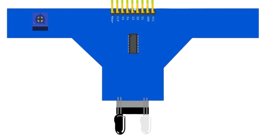
The 5-Channel IR (Infrared) Sensor is an electronic device capable of detecting infrared light across five distinct channels. This sensor is commonly used in line-following robots, edge detection, and object sorting based on reflective properties. It is particularly popular in educational robotics and automation projects.
Explore Projects Built with 5 channel IR sensor
Arduino Nano-Based 5-Channel IR Sensor System for Object Detection
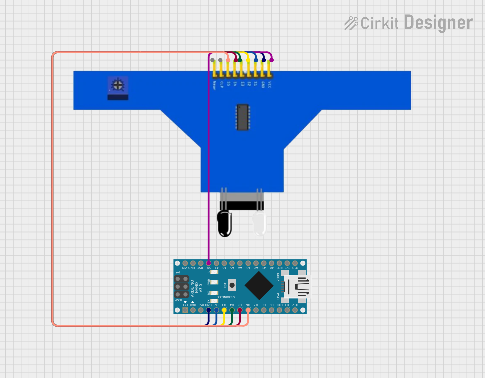
This circuit consists of a 5-channel IR sensor connected to an Arduino Nano. The Arduino Nano reads the sensor data from the IR sensor's five channels (S1 to S5) and is powered by the 5V and GND pins of the Arduino. The setup is likely intended for applications such as line-following robots or proximity sensing.
Battery-Powered IR Sensor Controlled Relay Module

This circuit uses an IR sensor to control a 1 Channel 5V Relay Module, which is powered by a 9V battery. The IR sensor detects an object and sends a signal to the relay module to switch its state, enabling or disabling the connected load.
Battery-Powered IR Sensor and AND Gate Circuit with LED Indicator
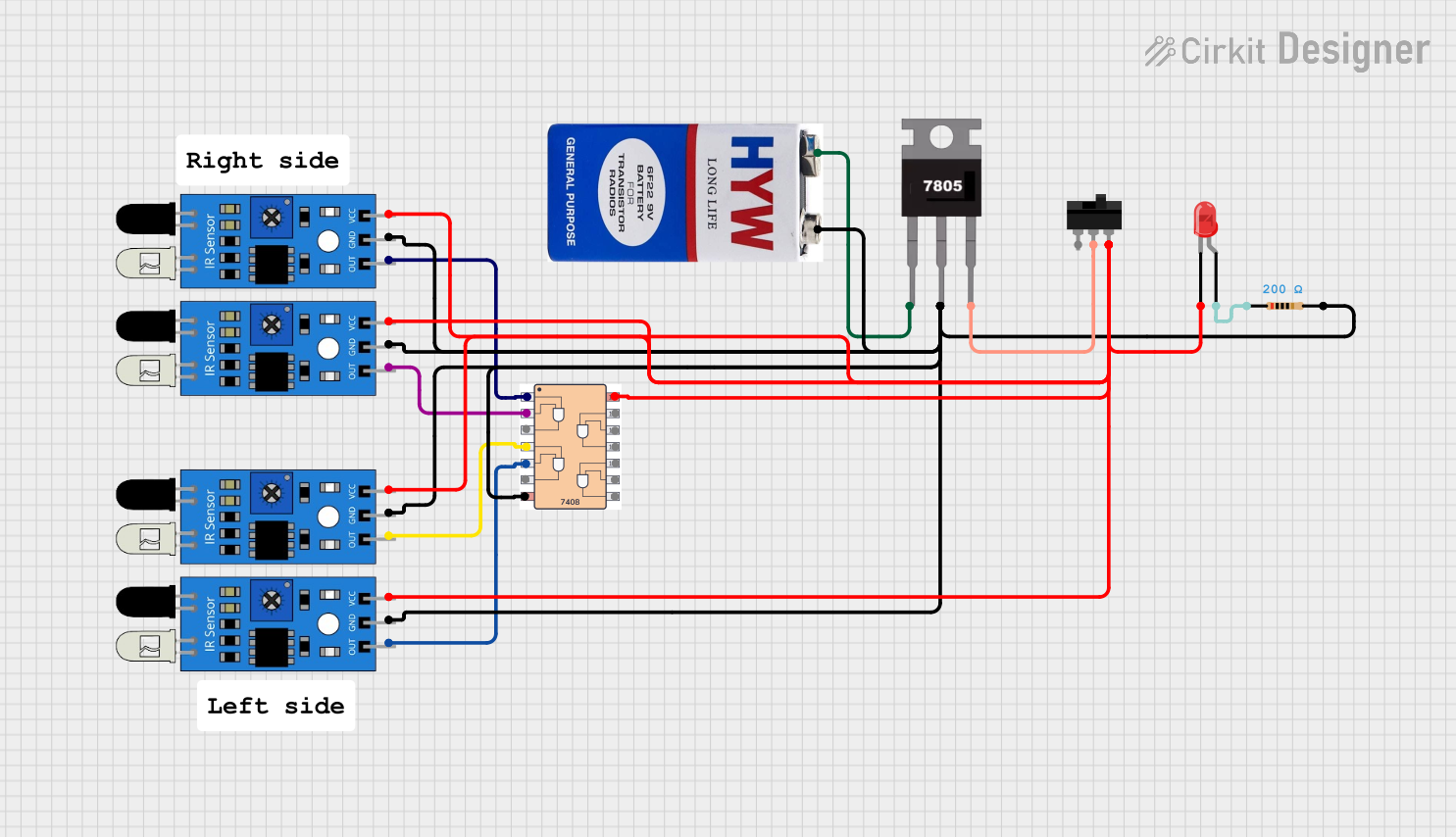
This circuit uses four IR sensors connected to a 7408 AND gate IC to detect the presence of objects. The output of the AND gate drives an LED indicator, with power regulated by a 7805 voltage regulator and controlled by a toggle switch.
Arduino-Based IR Sensor Array with LED Indicators
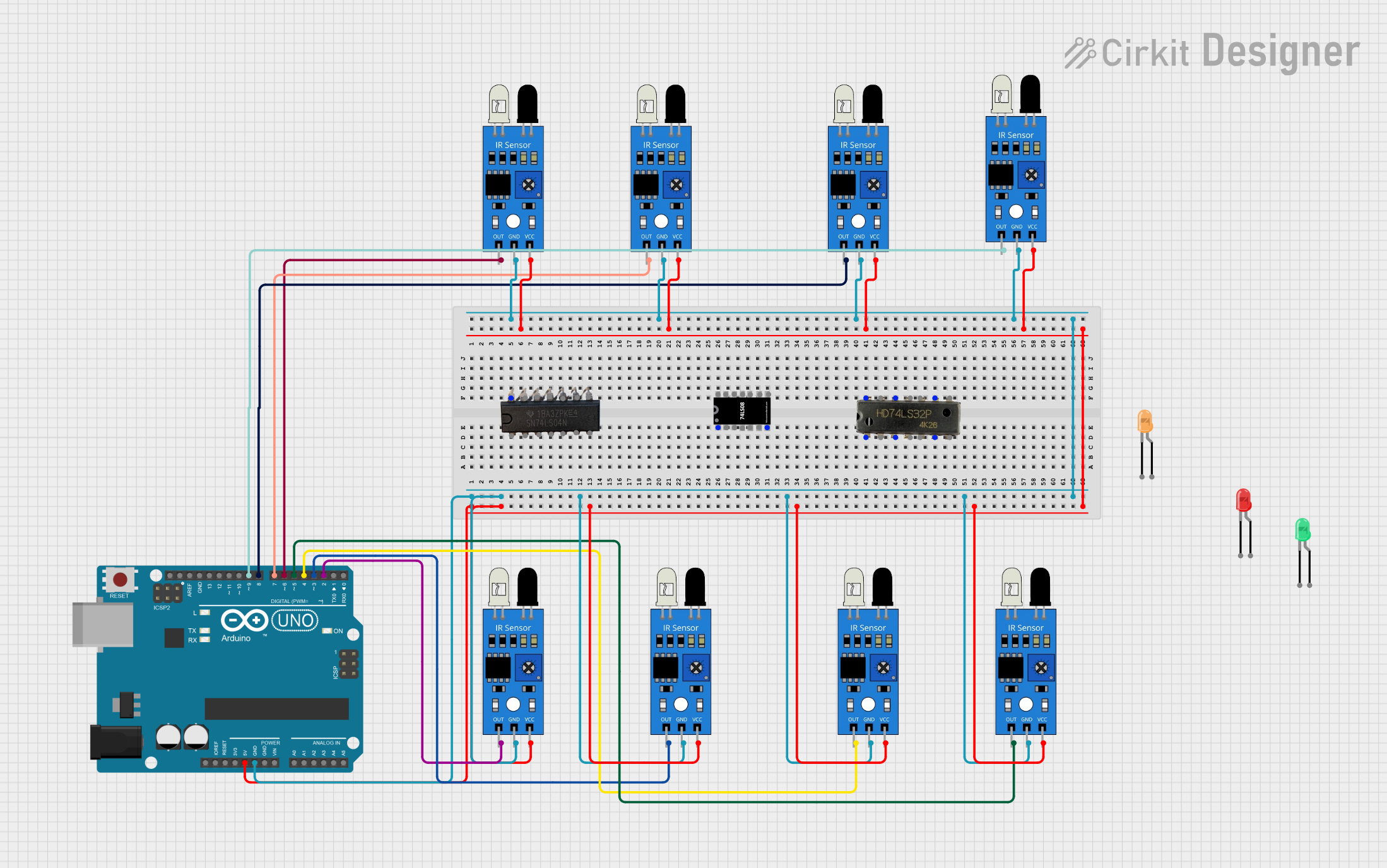
This circuit uses an Arduino UNO to interface with multiple IR sensors, each connected to a different digital input pin. The IR sensors are powered by the Arduino's 5V and GND pins, and the setup is likely intended for detecting objects or motion in various zones.
Explore Projects Built with 5 channel IR sensor
Arduino Nano-Based 5-Channel IR Sensor System for Object Detection
This circuit consists of a 5-channel IR sensor connected to an Arduino Nano. The Arduino Nano reads the sensor data from the IR sensor's five channels (S1 to S5) and is powered by the 5V and GND pins of the Arduino. The setup is likely intended for applications such as line-following robots or proximity sensing.
Battery-Powered IR Sensor Controlled Relay Module
This circuit uses an IR sensor to control a 1 Channel 5V Relay Module, which is powered by a 9V battery. The IR sensor detects an object and sends a signal to the relay module to switch its state, enabling or disabling the connected load.
Battery-Powered IR Sensor and AND Gate Circuit with LED Indicator
This circuit uses four IR sensors connected to a 7408 AND gate IC to detect the presence of objects. The output of the AND gate drives an LED indicator, with power regulated by a 7805 voltage regulator and controlled by a toggle switch.
Arduino-Based IR Sensor Array with LED Indicators
This circuit uses an Arduino UNO to interface with multiple IR sensors, each connected to a different digital input pin. The IR sensors are powered by the Arduino's 5V and GND pins, and the setup is likely intended for detecting objects or motion in various zones.
Common Applications and Use Cases
- Line following robots for competitions or educational purposes
- Edge detection to prevent robots from falling off tables
- Object detection and sorting systems based on IR reflectivity
- Multi-point proximity sensing in interactive installations
Technical Specifications
Key Technical Details
- Operating Voltage: 3.3V to 5V DC
- Current Consumption: 10-20mA per channel
- Output Channel: 5 digital outputs, one for each IR sensor
- Detection Distance: 2cm to 15cm (adjustable via onboard potentiometers)
- Ambient Light Resistance: Built-in daylight filter for outdoor use
Pin Configuration and Descriptions
| Pin Number | Description |
|---|---|
| 1 | VCC (Power Supply) |
| 2 | GND (Ground) |
| 3 | OUT1 (Channel 1) |
| 4 | OUT2 (Channel 2) |
| 5 | OUT3 (Channel 3) |
| 6 | OUT4 (Channel 4) |
| 7 | OUT5 (Channel 5) |
Usage Instructions
How to Use the Component in a Circuit
- Powering the Sensor: Connect the VCC pin to a 3.3V or 5V power supply and the GND pin to the ground of your circuit.
- Connecting to a Microcontroller: Connect each OUT pin to a digital input pin on your microcontroller, such as an Arduino UNO.
- Calibration: Adjust the onboard potentiometers to set the detection distance for each channel.
- Reading the Sensor: Monitor the digital input pins. A HIGH signal typically indicates that the IR light is being reflected back to the sensor, while a LOW signal indicates no reflection.
Important Considerations and Best Practices
- Ensure that the sensor is not exposed to direct sunlight or strong IR sources, which may interfere with its operation.
- Avoid placing reflective materials too close to the sensor, as this might cause false detections.
- Use pull-up or pull-down resistors on the digital output lines if your microcontroller requires them.
Example Arduino Code
// Define the sensor output pins
const int sensorPins[5] = {2, 3, 4, 5, 6};

void setup() {
  // Initialize each sensor pin as an input
  for (int i = 0; i < 5; i++) {
    pinMode(sensorPins[i], INPUT);
  }
  Serial.begin(9600);
}

void loop() {
  // Read and print the state of each sensor
  for (int i = 0; i < 5; i++) {
    int sensorState = digitalRead(sensorPins[i]);
    Serial.print("Sensor ");
    Serial.print(i + 1);
    Serial.print(": ");
    Serial.println(sensorState);
  }
  delay(100); // Short delay before the next reading
}
Troubleshooting and FAQs
Common Issues Users Might Face
- Inconsistent Readings: Ensure that the sensors are properly calibrated for the surface and ambient light conditions.
- No Output Signal: Check the power supply connections and ensure that the sensor is receiving the correct voltage.
- Interference from Ambient Light: Use the sensor in an environment with controlled lighting or adjust the onboard filters.
Solutions and Tips for Troubleshooting
- Calibration: Regularly calibrate the sensors for the specific application to maintain accuracy.
- Wiring Check: Verify all connections are secure and that there are no loose wires or shorts.
- Code Debugging: Use serial output to debug the sensor states and ensure the microcontroller is correctly reading the sensor outputs.
Remember to always power down your circuit before making any changes to prevent damage to the sensor or other components.