How to Use DC/DC: Examples, Pinouts, and Specs
Introduction
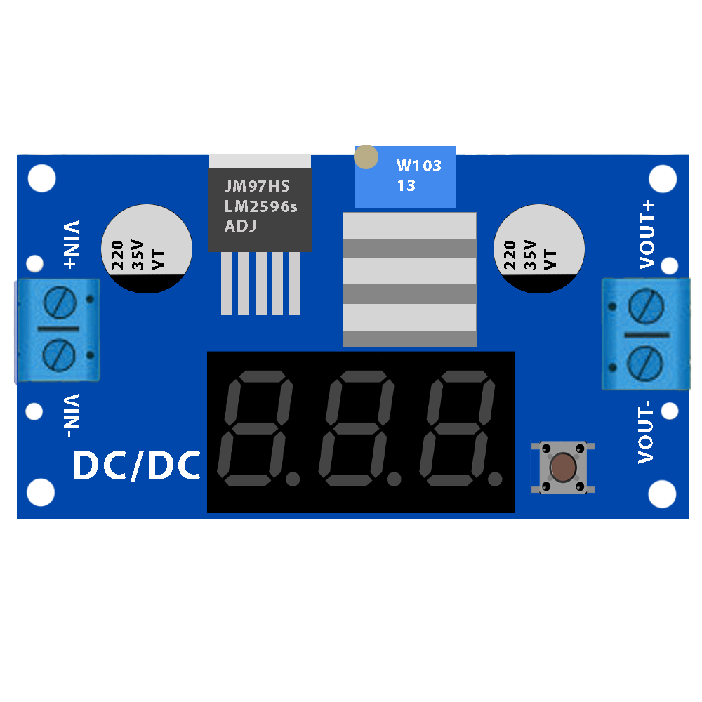
A DC/DC converter, manufactured by Basti (Part ID: DC/DC), is an electronic circuit designed to convert a direct current (DC) voltage from one level to another. This component is essential for efficient power management in a wide range of applications, including portable electronics, automotive systems, renewable energy systems, and industrial equipment. By stepping up, stepping down, or regulating voltage levels, the DC/DC converter ensures that devices receive the appropriate power supply for optimal performance.
Explore Projects Built with DC/DC


Explore Projects Built with DC/DC
Common Applications and Use Cases
- Portable Electronics: Powering devices like smartphones, tablets, and laptops.
- Automotive Systems: Voltage regulation for electric vehicles and onboard electronics.
- Renewable Energy: Managing power from solar panels or batteries.
- Industrial Equipment: Providing stable power to sensors, controllers, and actuators.
- Telecommunications: Powering base stations and network equipment.
Technical Specifications
The Basti DC/DC converter is designed to deliver reliable performance across a variety of applications. Below are the key technical specifications:
General Specifications
| Parameter | Value |
|---|---|
| Input Voltage Range | 4.5V to 36V |
| Output Voltage Range | 1.2V to 24V |
| Maximum Output Current | 3A |
| Efficiency | Up to 95% |
| Switching Frequency | 300 kHz to 1 MHz |
| Operating Temperature | -40°C to +85°C |
| Package Type | SMD (Surface-Mount Device) |
Pin Configuration and Descriptions
| Pin Number | Pin Name | Description |
|---|---|---|
| 1 | VIN | Input voltage pin. Connect to the DC power source. |
| 2 | GND | Ground pin. Connect to the system ground. |
| 3 | VOUT | Output voltage pin. Provides the regulated DC output. |
| 4 | EN | Enable pin. High to enable the converter, low to disable. |
| 5 | FB | Feedback pin. Used to set the output voltage via a resistor divider. |
| 6 | SW | Switching pin. Connects to the inductor in the circuit. |
Usage Instructions
How to Use the DC/DC Converter in a Circuit
- Input Voltage Connection: Connect the VIN pin to a DC power source within the specified input voltage range (4.5V to 36V).
- Output Voltage Configuration: Use a resistor divider network connected to the FB pin to set the desired output voltage. Refer to the formula in the datasheet for precise calculations.
- Inductor and Capacitor Selection: Choose an appropriate inductor and input/output capacitors based on the desired output current and voltage ripple.
- Enable/Disable Control: Use the EN pin to enable or disable the converter. Pull the pin high to enable and low to disable.
- Ground Connection: Ensure all ground connections are properly tied to the GND pin to avoid noise or instability.
Important Considerations and Best Practices
- Thermal Management: Ensure adequate heat dissipation, especially at high currents. Use a heat sink or place the component on a PCB with good thermal conductivity.
- Input/Output Filtering: Add input and output capacitors to minimize voltage ripple and noise.
- Inductor Selection: Choose an inductor with a current rating higher than the maximum output current to prevent saturation.
- PCB Layout: Minimize the length of high-current traces and place the input/output capacitors close to the component for optimal performance.
Example: Using the DC/DC Converter with an Arduino UNO
Below is an example of how to use the DC/DC converter to power an Arduino UNO with a 5V output:
Circuit Connections
- Connect a 12V DC power source to the VIN pin.
- Set the output voltage to 5V using a resistor divider on the FB pin.
- Connect the VOUT pin to the Arduino UNO's 5V input pin.
- Tie the GND pin to the Arduino's ground.
Arduino Code Example
// Example code to blink an LED using an Arduino UNO powered by the DC/DC converter

const int ledPin = 13; // Pin connected to the onboard LED

void setup() {
  pinMode(ledPin, OUTPUT); // Set the LED pin as an output
}

void loop() {
  digitalWrite(ledPin, HIGH); // Turn the LED on
  delay(1000);               // Wait for 1 second
  digitalWrite(ledPin, LOW);  // Turn the LED off
  delay(1000);               // Wait for 1 second
}
Troubleshooting and FAQs
Common Issues and Solutions
No Output Voltage:
- Ensure the EN pin is pulled high to enable the converter.
- Verify that the input voltage is within the specified range.
- Check for proper connections and soldering on the PCB.
Excessive Heat:
- Verify that the load current does not exceed the maximum output current (3A).
- Ensure proper thermal management, such as using a heat sink or thermal vias.
Output Voltage Instability:
- Check the feedback resistor network for correct values.
- Ensure that the input and output capacitors are of the recommended type and value.
- Minimize noise by improving PCB layout and grounding.
High Voltage Ripple:
- Increase the capacitance of the output capacitor.
- Use low-ESR capacitors for better performance.
FAQs
Q1: Can the DC/DC converter handle reverse polarity on the input?
A1: No, the DC/DC converter does not have built-in reverse polarity protection. Use a diode or protection circuit to prevent damage.
Q2: How do I calculate the resistor values for the feedback network?
A2: Use the formula provided in the datasheet:
[
V_{OUT} = V_{REF} \times \left(1 + \frac{R1}{R2}\right)
]
Where ( V_{REF} ) is the reference voltage (typically 1.2V), and ( R1 ) and ( R2 ) are the feedback resistors.
Q3: Can this converter be used for battery charging applications?
A3: Yes, but ensure that the output voltage and current are configured to match the battery's charging requirements.
Q4: What is the maximum efficiency of the converter?
A4: The maximum efficiency is up to 95%, depending on the input/output voltage and load conditions.