How to Use FC/Companion Computer Bundle: Examples, Pinouts, and Specs
Introduction
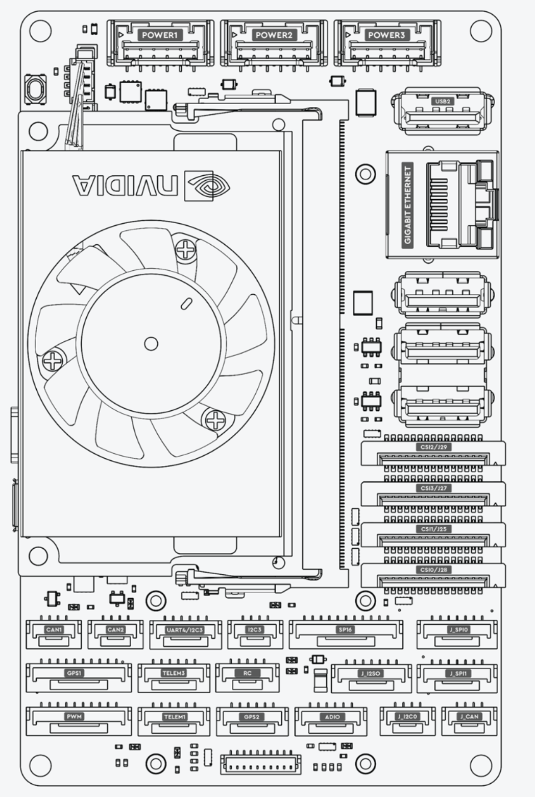
The FC/Companion Computer Bundle (Manufacturer Part ID: Ark Jetson Orin NX) by ARK Electronics is a cutting-edge combination of a flight controller (FC) and a companion computer. This bundle is specifically designed for drones and robotics applications, providing advanced processing, navigation, and communication capabilities. The integration of a high-performance companion computer with a robust flight controller enables real-time decision-making, AI-based processing, and seamless control of autonomous systems.
Explore Projects Built with FC/Companion Computer Bundle


Explore Projects Built with FC/Companion Computer Bundle
Common Applications and Use Cases
- Autonomous drones for delivery, surveillance, and mapping
- Robotics systems requiring AI-based navigation and object detection
- Industrial automation and inspection systems
- Research and development in autonomous vehicles and robotics
- Swarm robotics and multi-agent systems
Technical Specifications
Key Technical Details
| Parameter | Specification |
|---|---|
| Processor (Companion) | NVIDIA Jetson Orin NX (up to 100 TOPS AI performance) |
| Flight Controller MCU | STM32H7 series (32-bit ARM Cortex-M7, 480 MHz) |
| Operating Voltage | 5V - 12V DC |
| Power Consumption | 15W (typical), 25W (maximum under load) |
| Communication Interfaces | UART, I2C, SPI, CAN, USB 3.1, Ethernet |
| Storage | 16GB eMMC (expandable via microSD or NVMe SSD) |
| GPIO Pins | 40 (programmable, 3.3V logic level) |
| IMU (Inertial Measurement Unit) | 6-axis gyroscope and accelerometer, magnetometer |
| GNSS Support | GPS, GLONASS, Galileo, BeiDou |
| Dimensions | 100mm x 80mm x 25mm |
| Weight | 150g |
| Operating Temperature | -20°C to 70°C |
Pin Configuration and Descriptions
Flight Controller Pinout
| Pin Name | Type | Description |
|---|---|---|
| GND | Power | Ground connection |
| VCC | Power | Power input (5V - 12V DC) |
| RX1/TX1 | UART | Serial communication port 1 |
| RX2/TX2 | UART | Serial communication port 2 |
| SCL/SDA | I2C | I2C communication lines |
| CS/SCK/MISO/MOSI | SPI | SPI communication lines |
| PWM1-8 | PWM Output | Motor control or servo outputs |
| CAN_H/CAN_L | CAN Bus | CAN bus communication lines |
| GPIO1-10 | GPIO | General-purpose input/output pins |
Companion Computer Pinout
| Pin Name | Type | Description |
|---|---|---|
| USB 3.1 | USB | High-speed USB interface for peripherals |
| ETH | Ethernet | Gigabit Ethernet for networking |
| HDMI | Video Output | HDMI output for display connection |
| NVMe | Storage | NVMe SSD interface for additional storage |
| GPIO1-30 | GPIO | General-purpose input/output pins |
| UART1/UART2 | UART | Serial communication ports |
| I2C1/I2C2 | I2C | I2C communication lines |
| SPI1/SPI2 | SPI | SPI communication lines |
Usage Instructions
How to Use the Component in a Circuit
- Power Supply: Connect the bundle to a stable DC power source (5V - 12V). Ensure the power supply can handle the maximum power consumption of 25W.
- Peripheral Connections:
- Use the PWM outputs on the flight controller to connect motors or servos.
- Connect sensors (e.g., LiDAR, cameras) to the companion computer via USB, I2C, or SPI.
- Communication Setup:
- Use UART, CAN, or Ethernet for communication between the flight controller and other devices.
- Configure the companion computer to communicate with the flight controller via UART or CAN.
- Software Configuration:
- Install the required firmware on the flight controller (e.g., PX4 or ArduPilot).
- Set up the companion computer with the desired operating system (e.g., Ubuntu 20.04 with NVIDIA JetPack SDK).
- Use ROS (Robot Operating System) for robotics applications and AI-based processing.
Important Considerations and Best Practices
- Cooling: Ensure adequate cooling for the companion computer, especially during high-load operations.
- Power Management: Use a power distribution board (PDB) to manage power for motors, sensors, and the bundle.
- Firmware Updates: Regularly update the firmware for both the flight controller and the companion computer to ensure compatibility and access to the latest features.
- Isolation: Use proper electrical isolation for sensitive components to prevent noise interference.
- Testing: Test the system in a controlled environment before deploying it in real-world applications.
Example Code for Arduino UNO Integration
The following example demonstrates how to send data from an Arduino UNO to the flight controller via UART.
#include <SoftwareSerial.h>

// Define RX and TX pins for software serial communication
SoftwareSerial mySerial(10, 11); // RX = pin 10, TX = pin 11

void setup() {
  // Initialize hardware serial for debugging
  Serial.begin(9600);
  while (!Serial) {
    ; // Wait for the serial port to connect
  }
  Serial.println("Arduino to FC Communication Example");

  // Initialize software serial for communication with the flight controller
  mySerial.begin(115200);
}

void loop() {
  // Send a test message to the flight controller
  mySerial.println("Hello, Flight Controller!");

  // Check if data is received from the flight controller
  if (mySerial.available()) {
    String receivedData = mySerial.readString();
    Serial.print("Received from FC: ");
    Serial.println(receivedData);
  }

  delay(1000); // Wait for 1 second before sending the next message
}
Troubleshooting and FAQs
Common Issues and Solutions
No Power to the Bundle:
- Cause: Insufficient power supply or incorrect wiring.
- Solution: Verify the power supply voltage and current ratings. Check all connections.
Communication Failure Between FC and Companion Computer:
- Cause: Incorrect UART or CAN configuration.
- Solution: Ensure the baud rate and communication settings match on both devices.
Overheating:
- Cause: Insufficient cooling for the companion computer.
- Solution: Add a heatsink or active cooling (e.g., a fan) to the companion computer.
Motors Not Responding:
- Cause: Incorrect PWM configuration or wiring.
- Solution: Verify the motor connections and ensure the flight controller firmware is properly configured.
Sensor Data Not Detected:
- Cause: Incorrect sensor wiring or communication protocol mismatch.
- Solution: Double-check the sensor connections and ensure the correct protocol (I2C, SPI, etc.) is used.
FAQs
Q: Can I use this bundle for fixed-wing drones?
- A: Yes, the flight controller supports fixed-wing, multirotor, and VTOL configurations.
Q: What operating systems are supported on the companion computer?
- A: The companion computer supports Linux-based operating systems, including Ubuntu with NVIDIA JetPack SDK.
Q: How do I update the firmware on the flight controller?
- A: Use a USB connection and a compatible ground control software (e.g., QGroundControl) to update the firmware.
Q: Can I expand the storage on the companion computer?
- A: Yes, you can use a microSD card or an NVMe SSD for additional storage.
Q: Is this bundle compatible with ROS 2?
- A: Yes, the companion computer is fully compatible with ROS 2 for robotics applications.