Cirkit Designer Logo
Cirkit Designer
Your all-in-one circuit design IDE
Home / 
Component Documentation

How to Use KY-033 Line Tracking Sensor: Examples, Pinouts, and Specs
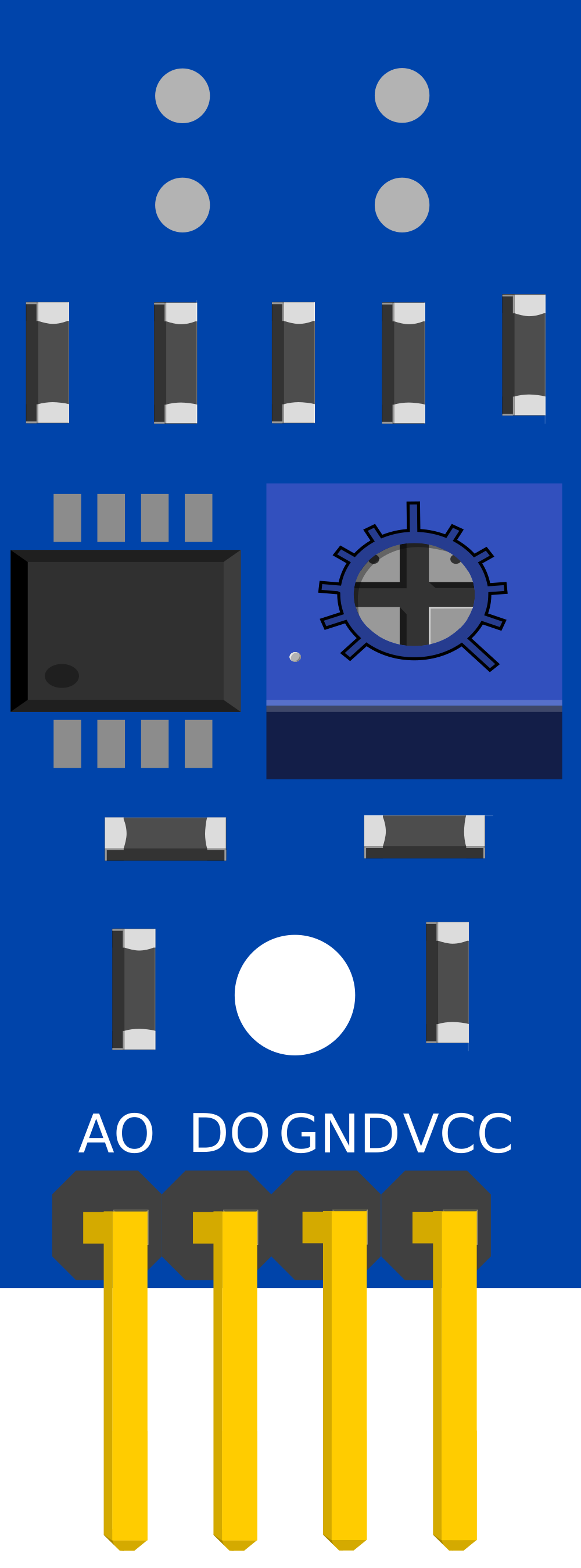
Image of KY-033 Line Tracking Sensor
Cirkit Designer LogoDesign with KY-033 Line Tracking Sensor in Cirkit Designer

Introduction

The KY-033 Line Tracking Sensor is an electronic module designed for robotics and automation applications. It utilizes an infrared emitter and receiver pair to detect reflective surfaces, making it ideal for line-following robots or obstacle detection along predetermined paths. This sensor is particularly useful in educational robotics and DIY projects where path tracking is required.

Explore Projects Built with KY-033 Line Tracking Sensor

Use Cirkit Designer to design, explore, and prototype these projects online. Some projects support real-time simulation. Click "Open Project" to start designing instantly!
Raspberry Pi Zero W Based Line Tracking and Obstacle Detection System
Image of CSC615-Assignment#4-LineSensor: A project utilizing KY-033 Line Tracking Sensor in a practical application
This circuit integrates a Raspberry Pi Zero W with two sensors: a KY-033 Line Tracking Sensor and an FC-51 IR Sensor. The Raspberry Pi is configured to receive digital input signals from the KY-033 sensor on GPIO 04 and from the FC-51 sensor on GPIO 24. The circuit is designed for object detection and line tracking applications, with the Raspberry Pi processing the sensor inputs for decision-making tasks.
Cirkit Designer LogoOpen Project in Cirkit Designer
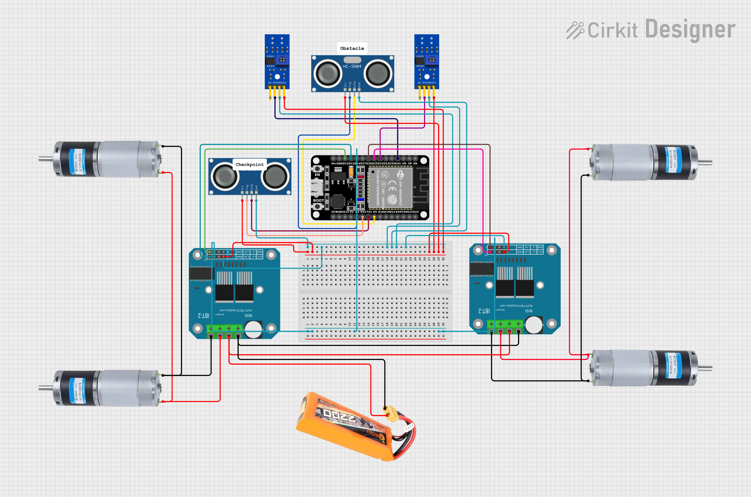
ESP32-Controlled Dual Ultrasonic Sensor and Line Tracking Robot
Image of Gilbert Project: A project utilizing KY-033 Line Tracking Sensor in a practical application
This circuit is designed for a robotic vehicle featuring obstacle detection and line tracking capabilities. It uses an ESP32 microcontroller to process signals from ultrasonic and line tracking sensors and to control motor drivers for vehicle propulsion. The system is powered by a lipo battery, and the ESP32 manages sensor inputs and motor outputs to navigate the vehicle autonomously.
Cirkit Designer LogoOpen Project in Cirkit Designer
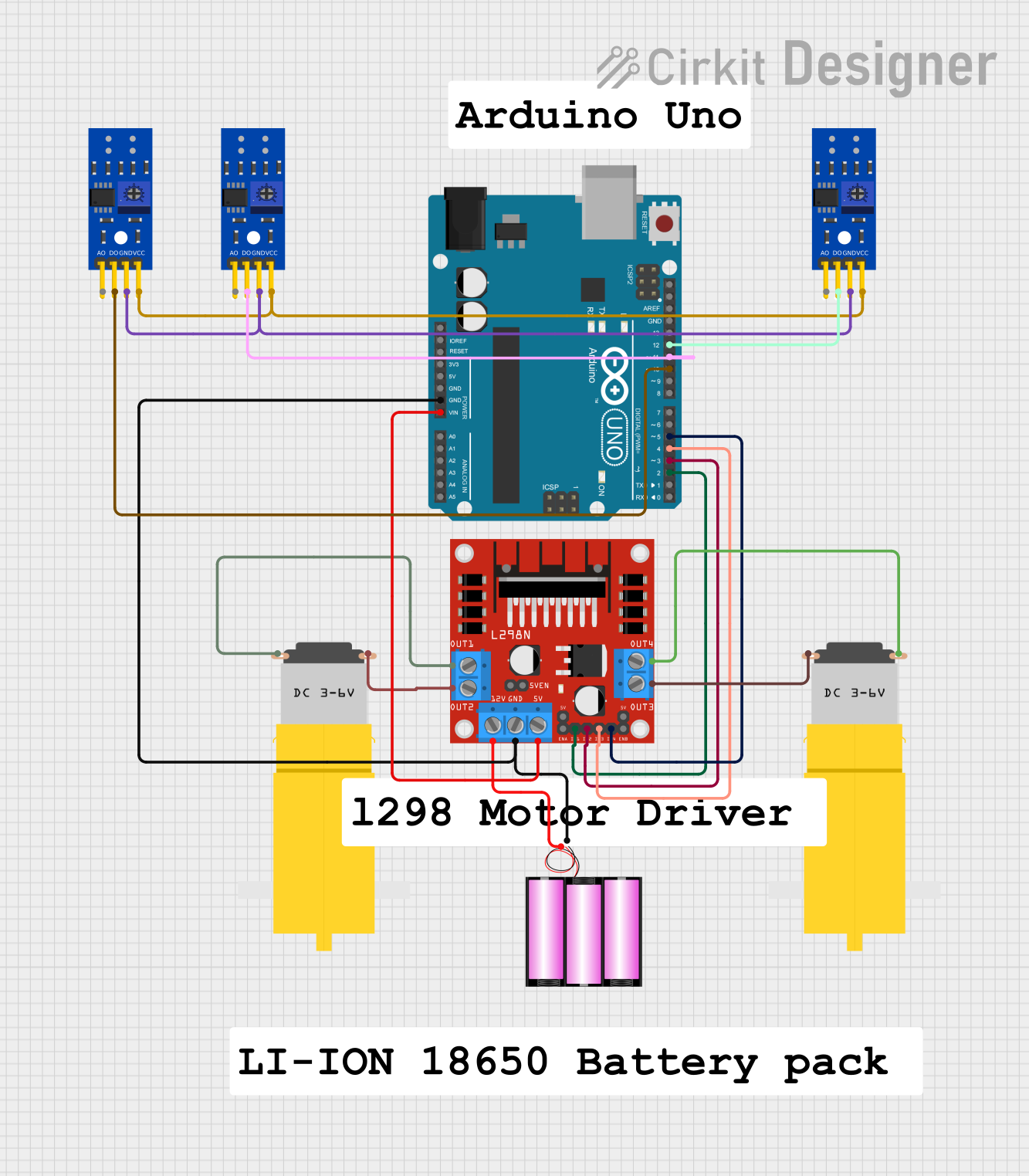
Arduino UNO Line Following Robot with L298N Motor Driver and KY-033 Sensors
Image of human following robot : A project utilizing KY-033 Line Tracking Sensor in a practical application
This circuit is a line-following robot controlled by an Arduino UNO. It uses three KY-033 line tracking sensors to detect the path and an L298N motor driver to control two DC motors, powered by a 12V battery. The Arduino processes sensor inputs to adjust motor speeds and directions, enabling the robot to follow a line.
Cirkit Designer LogoOpen Project in Cirkit Designer
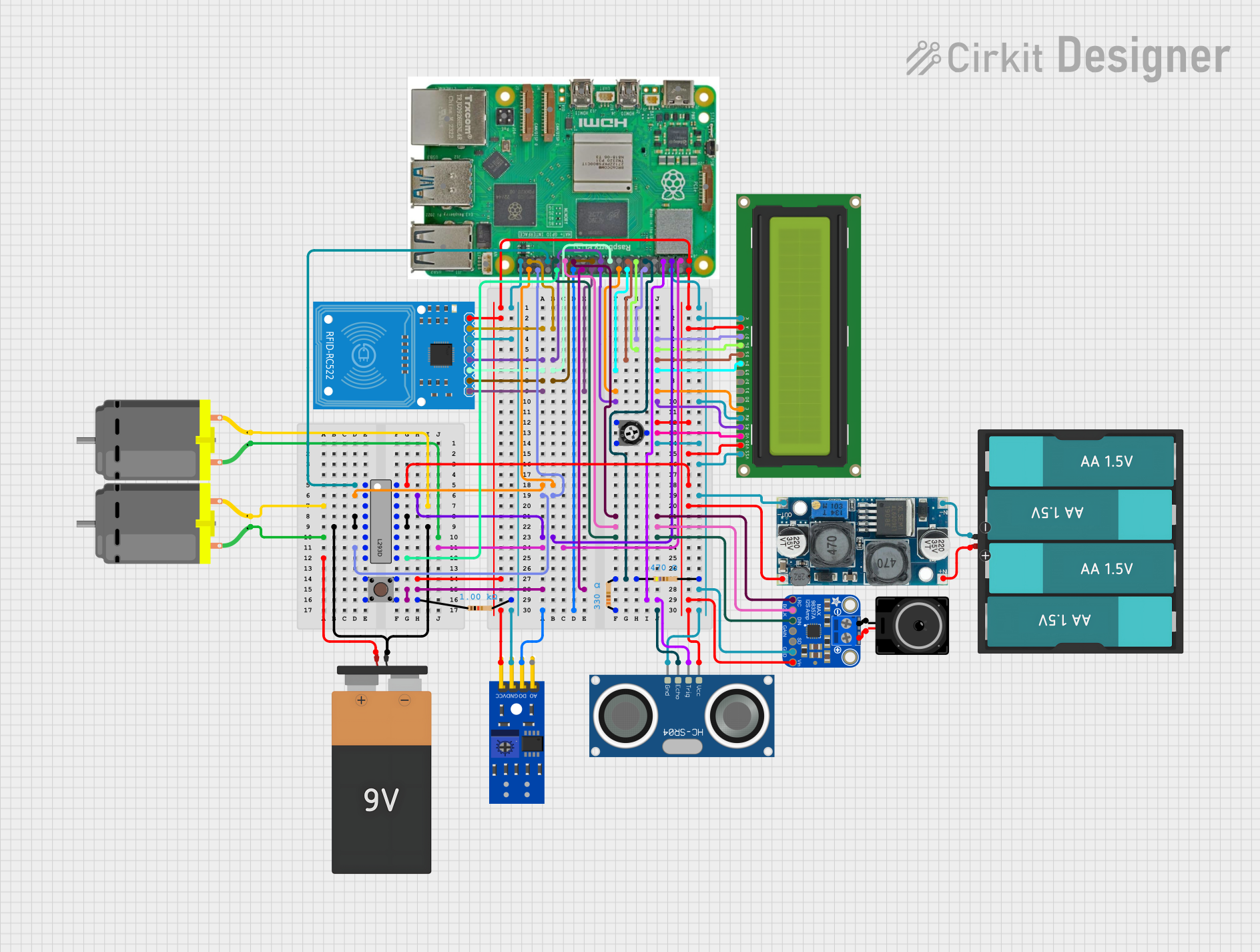
Raspberry Pi 5-Based Multifunctional Robotic Controller with RFID and Audio Output
Image of SpeedyPi: A project utilizing KY-033 Line Tracking Sensor in a practical application
This circuit features a Raspberry Pi 5 as the central controller, interfaced with various sensors and output devices. It includes an RFID-RC522 module for RFID reading, an HC-SR04 ultrasonic sensor for distance measurement, and a KY-033 line tracking sensor for detecting lines or edges. The circuit also controls two DC motors via an L293D motor driver, displays information on a 16x2 LCD, and outputs audio through an Adafruit MAX98357A I2S class-D amplifier connected to a loudspeaker. Power regulation is managed by an XL6009 voltage regulator, and user input is captured through a pushbutton. The circuit is likely designed for a mobile robot with line tracking, obstacle avoidance, RFID interaction, and audio feedback capabilities.
Cirkit Designer LogoOpen Project in Cirkit Designer

Explore Projects Built with KY-033 Line Tracking Sensor

Use Cirkit Designer to design, explore, and prototype these projects online. Some projects support real-time simulation. Click "Open Project" to start designing instantly!
Image of CSC615-Assignment#4-LineSensor: A project utilizing KY-033 Line Tracking Sensor in a practical application
Raspberry Pi Zero W Based Line Tracking and Obstacle Detection System
This circuit integrates a Raspberry Pi Zero W with two sensors: a KY-033 Line Tracking Sensor and an FC-51 IR Sensor. The Raspberry Pi is configured to receive digital input signals from the KY-033 sensor on GPIO 04 and from the FC-51 sensor on GPIO 24. The circuit is designed for object detection and line tracking applications, with the Raspberry Pi processing the sensor inputs for decision-making tasks.
Cirkit Designer LogoOpen Project in Cirkit Designer
Image of Gilbert Project: A project utilizing KY-033 Line Tracking Sensor in a practical application
ESP32-Controlled Dual Ultrasonic Sensor and Line Tracking Robot
This circuit is designed for a robotic vehicle featuring obstacle detection and line tracking capabilities. It uses an ESP32 microcontroller to process signals from ultrasonic and line tracking sensors and to control motor drivers for vehicle propulsion. The system is powered by a lipo battery, and the ESP32 manages sensor inputs and motor outputs to navigate the vehicle autonomously.
Cirkit Designer LogoOpen Project in Cirkit Designer
Image of human following robot : A project utilizing KY-033 Line Tracking Sensor in a practical application
Arduino UNO Line Following Robot with L298N Motor Driver and KY-033 Sensors
This circuit is a line-following robot controlled by an Arduino UNO. It uses three KY-033 line tracking sensors to detect the path and an L298N motor driver to control two DC motors, powered by a 12V battery. The Arduino processes sensor inputs to adjust motor speeds and directions, enabling the robot to follow a line.
Cirkit Designer LogoOpen Project in Cirkit Designer
Image of SpeedyPi: A project utilizing KY-033 Line Tracking Sensor in a practical application
Raspberry Pi 5-Based Multifunctional Robotic Controller with RFID and Audio Output
This circuit features a Raspberry Pi 5 as the central controller, interfaced with various sensors and output devices. It includes an RFID-RC522 module for RFID reading, an HC-SR04 ultrasonic sensor for distance measurement, and a KY-033 line tracking sensor for detecting lines or edges. The circuit also controls two DC motors via an L293D motor driver, displays information on a 16x2 LCD, and outputs audio through an Adafruit MAX98357A I2S class-D amplifier connected to a loudspeaker. Power regulation is managed by an XL6009 voltage regulator, and user input is captured through a pushbutton. The circuit is likely designed for a mobile robot with line tracking, obstacle avoidance, RFID interaction, and audio feedback capabilities.
Cirkit Designer LogoOpen Project in Cirkit Designer

Common Applications and Use Cases

  • Line-following robots for competitions or educational purposes
  • Automated guided vehicles (AGVs) in industrial settings
  • Boundary detection for robotic lawnmowers or vacuum cleaners
  • Positioning systems in conveyor belts or manufacturing lines

Technical Specifications

Key Technical Details

  • Operating Voltage: 3.3V to 5V DC
  • Current Consumption: 20mA (typical)
  • Output Type: Digital signal
  • Detection Distance: 2mm to 10mm
  • Sensor Type: Infrared reflective

Pin Configuration and Descriptions

Pin Number Pin Name Description
1 VCC Power supply (3.3V to 5V DC)
2 GND Ground connection
3 DO Digital output (0 or 1)

Usage Instructions

How to Use the Component in a Circuit

  1. Connect the VCC pin to the power supply (3.3V to 5V).
  2. Connect the GND pin to the ground of the power supply.
  3. Connect the DO pin to a digital input pin on a microcontroller, such as an Arduino UNO.

Important Considerations and Best Practices

  • Ensure that the sensor is mounted at the correct height from the surface (2mm to 10mm) for optimal detection.
  • Avoid exposing the sensor to direct sunlight or other strong infrared sources to prevent interference.
  • Use a pull-up resistor if the microcontroller input pin does not have an internal pull-up feature.
  • Test the sensor with different surface colors and materials to calibrate the sensitivity for your specific application.

Example Code for Arduino UNO

// KY-033 Line Tracking Sensor Example Code for Arduino UNO

const int LineSensorPin = 2; // Digital pin connected to the sensor's DO pin

void setup() {
  pinMode(LineSensorPin, INPUT); // Initialize the line sensor pin as an input
  Serial.begin(9600);           // Start serial communication at 9600 baud rate
}

void loop() {
  int lineState = digitalRead(LineSensorPin); // Read the sensor state (HIGH or LOW)
  
  // Check if the sensor detects a line
  if (lineState == LOW) {
    // Line detected
    Serial.println("Line Detected!");
  } else {
    // No line detected
    Serial.println("No Line Detected.");
  }
  
  delay(200); // Wait for 200 milliseconds before reading again
}

Troubleshooting and FAQs

Common Issues Users Might Face

  • Sensor not detecting line: Ensure that the sensor is properly connected and the surface is within the detection range.
  • False detections: Check for ambient infrared light interference and adjust the sensor's position or orientation.
  • Inconsistent readings: Verify that the sensor is mounted stably and is not subject to vibrations or sudden movements.

Solutions and Tips for Troubleshooting

  • If the sensor is not functioning, check all connections and ensure that the power supply is within the specified voltage range.
  • Calibrate the sensor by testing it on different surfaces and adjusting the height if necessary.
  • Use a multimeter to check the voltage levels at the VCC and DO pins to ensure proper operation.

FAQs

Q: Can the KY-033 sensor detect any color of line? A: The sensor is best at detecting lines that have a high contrast with the background, typically dark lines on a light surface.

Q: What is the output of the sensor when a line is detected? A: The digital output (DO) pin will typically output a LOW signal when a line is detected.

Q: How can I adjust the sensitivity of the sensor? A: The KY-033 sensor usually comes with a potentiometer that can be adjusted to change the sensitivity. Rotate the potentiometer while monitoring the sensor's output until the desired sensitivity is achieved.

Q: Is it possible to use the KY-033 sensor with a 3.3V system? A: Yes, the sensor can operate at a voltage as low as 3.3V, making it compatible with 3.3V systems like some ARM-based microcontrollers.