How to Use STorM32 micro motor v252E: Examples, Pinouts, and Specs
Introduction
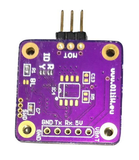
The STorM32 micro motor v252E, manufactured by Olliw42 (Part ID: BOTTOM), is a compact and lightweight brushless motor designed for high-performance applications. It features advanced control capabilities and efficient power usage, making it an ideal choice for drones, robotics, and other precision motion control systems. Its small form factor and robust design allow it to deliver reliable performance in demanding environments.
Explore Projects Built with STorM32 micro motor v252E
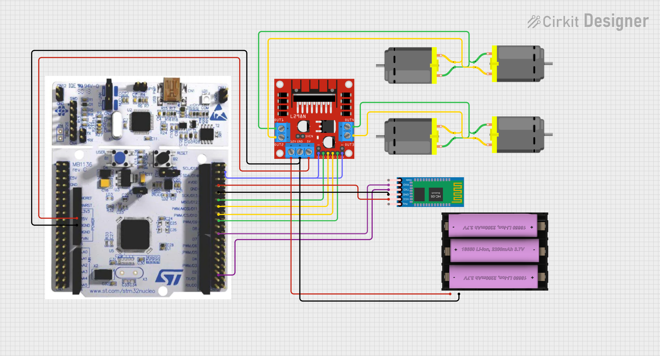
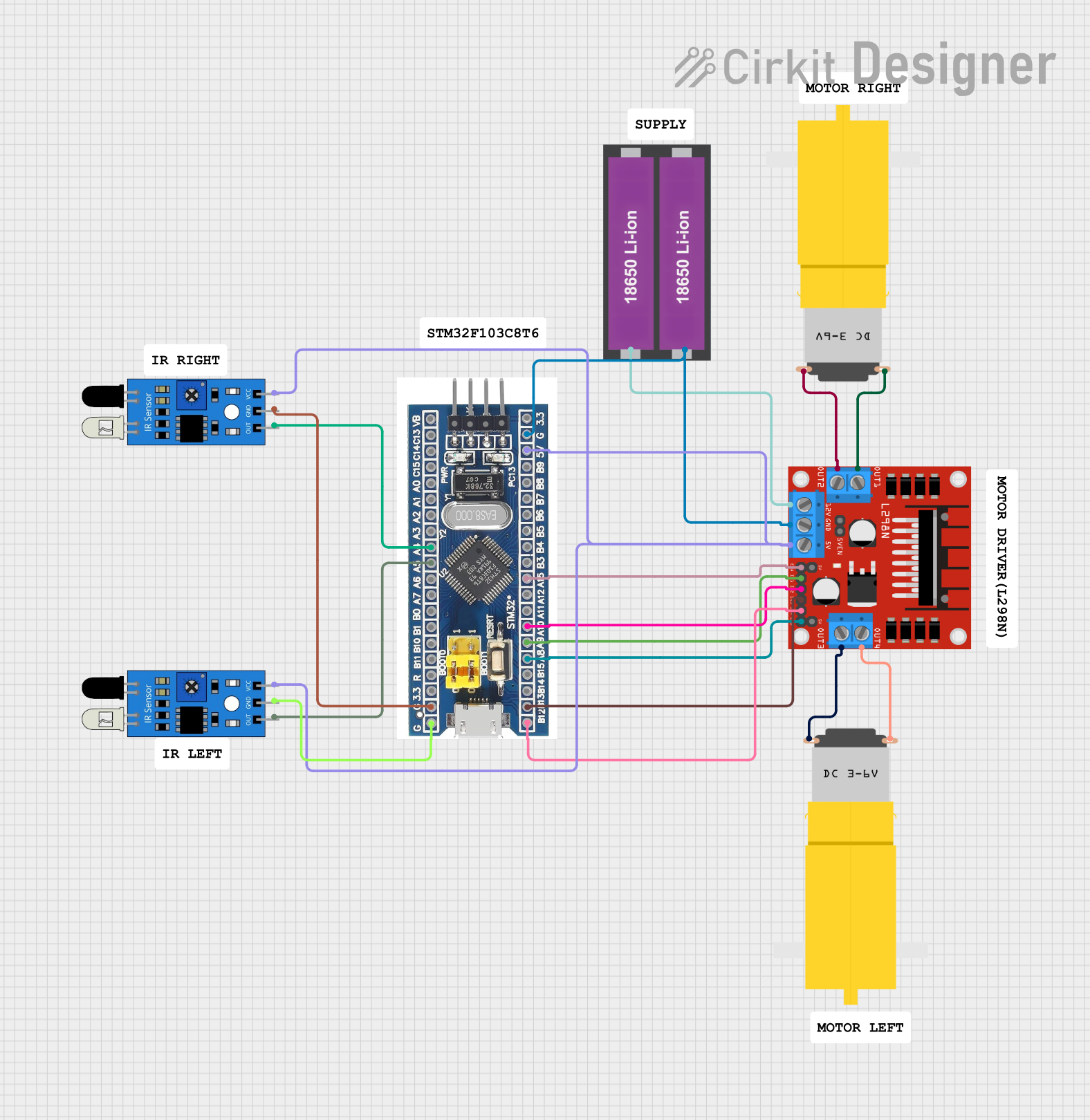
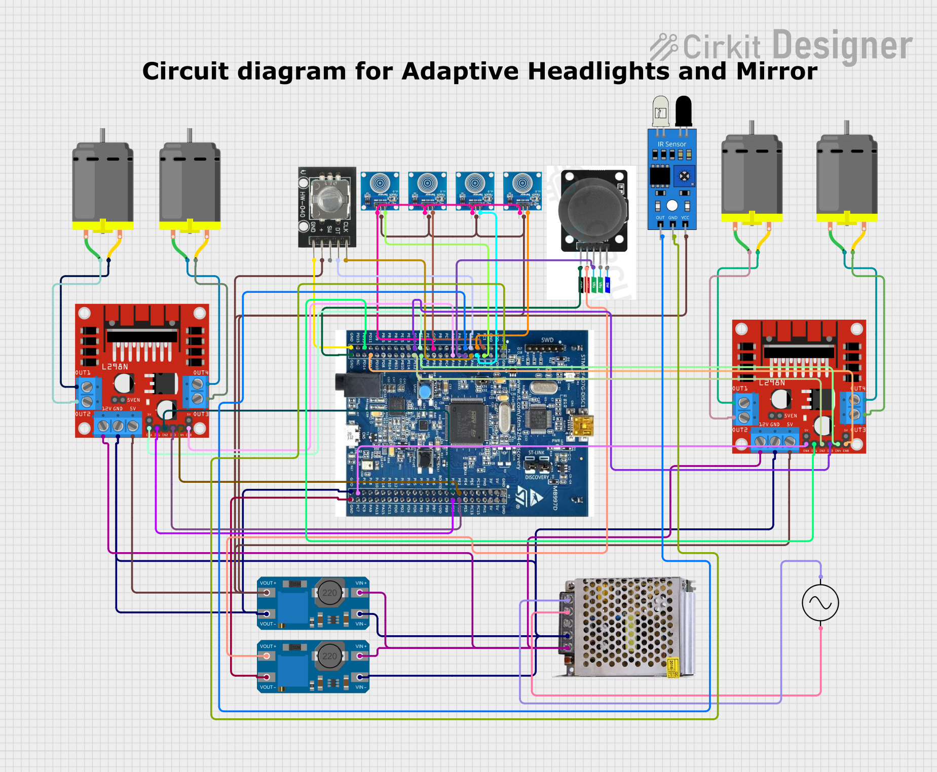

Explore Projects Built with STorM32 micro motor v252E
Common Applications
- Multirotor drones for stable and efficient flight
- Robotic arms and precision motion systems
- Gimbal stabilization systems
- Small-scale industrial automation
- Educational and hobbyist projects requiring compact motors
Technical Specifications
Key Technical Details
| Parameter | Value |
|---|---|
| Manufacturer | Olliw42 |
| Part ID | BOTTOM |
| Motor Type | Brushless DC (BLDC) |
| Voltage Range | 6V - 24V |
| Maximum Current | 2.5A |
| Power Rating | 60W |
| Motor KV Rating | 2200 KV |
| Dimensions | 22mm x 22mm x 10mm |
| Weight | 15g |
| Operating Temperature | -20°C to 60°C |
| Control Interface | PWM (Pulse Width Modulation) |
Pin Configuration and Descriptions
The STorM32 micro motor v252E has three primary connection points for operation. These are the standard connections for a brushless motor.
| Pin Name | Description |
|---|---|
| A | Motor phase A connection |
| B | Motor phase B connection |
| C | Motor phase C connection |
Note: This motor requires an external brushless motor controller (ESC) to operate. Ensure the ESC is compatible with the motor's voltage and current ratings.
Usage Instructions
How to Use the Component in a Circuit
Connect the Motor to an ESC:
- Connect the three motor wires (A, B, C) to the corresponding output terminals of the ESC. The order of connection determines the motor's rotation direction. If the motor spins in the wrong direction, swap any two wires.
Power the ESC:
- Supply the ESC with a voltage within the motor's operating range (6V - 24V). Ensure the power supply can handle the motor's maximum current draw (2.5A).
Control the Motor via PWM:
- Use a microcontroller (e.g., Arduino UNO) to send PWM signals to the ESC's control input. The PWM signal determines the motor's speed and direction.
Secure the Motor:
- Mount the motor securely to your application using appropriate screws or brackets. Ensure there is no obstruction to the motor's rotation.
Important Considerations and Best Practices
- Cooling: Although the motor is efficient, prolonged operation at high power may generate heat. Ensure adequate ventilation or cooling to prevent overheating.
- ESC Compatibility: Use an ESC that matches the motor's voltage and current specifications. A mismatch can lead to poor performance or damage.
- PWM Signal: Ensure the PWM signal frequency and duty cycle are compatible with the ESC. Most ESCs operate at a PWM frequency of 50Hz.
- Startup Calibration: Some ESCs require calibration during the first use. Follow the ESC manufacturer's instructions for calibration.
Example: Using the Motor with an Arduino UNO
Below is an example of controlling the motor using an Arduino UNO and a compatible ESC.
#include <Servo.h> // Include the Servo library to generate PWM signals

Servo esc; // Create a Servo object to control the ESC

void setup() {
  esc.attach(9); // Connect the ESC signal wire to pin 9 on the Arduino
  esc.writeMicroseconds(1000); // Send minimum throttle signal to arm the ESC
  delay(2000); // Wait for 2 seconds to allow the ESC to initialize
}

void loop() {
  esc.writeMicroseconds(1500); // Set throttle to 50% (1500us PWM signal)
  delay(5000); // Run the motor at 50% speed for 5 seconds

  esc.writeMicroseconds(1000); // Stop the motor (minimum throttle)
  delay(5000); // Wait for 5 seconds before restarting
}
Note: Adjust the
writeMicrosecondsvalues based on your ESC's throttle range (typically 1000us to 2000us).
Troubleshooting and FAQs
Common Issues and Solutions
Motor Does Not Spin
- Cause: Incorrect wiring or ESC not armed.
- Solution: Double-check the motor and ESC connections. Ensure the ESC is receiving a valid PWM signal and is properly armed.
Motor Spins in the Wrong Direction
- Cause: Incorrect phase wire connections.
- Solution: Swap any two of the three motor wires (A, B, C) to reverse the direction.
Motor Overheats
- Cause: Prolonged operation at high power or insufficient cooling.
- Solution: Reduce the load on the motor or improve ventilation around the motor.
ESC Beeps Continuously
- Cause: ESC is not receiving a valid PWM signal or is not calibrated.
- Solution: Verify the PWM signal from the microcontroller. If necessary, recalibrate the ESC following the manufacturer's instructions.
Motor Vibrates Excessively
- Cause: Imbalanced load or loose mounting.
- Solution: Check the motor's mounting and ensure the load (e.g., propeller) is balanced.
FAQs
Q: Can I use this motor without an ESC?
A: No, the STorM32 micro motor v252E requires an external ESC to operate. The ESC provides the necessary commutation and control signals.
Q: What is the maximum propeller size this motor can handle?
A: The maximum propeller size depends on the application and load. For drones, a 5-inch propeller is typically suitable, but always test within the motor's power limits.
Q: Can I use this motor with a 3.3V microcontroller?
A: Yes, but ensure the ESC is compatible with 3.3V PWM signals. If not, use a level shifter to convert the signal to 5V.
Q: How do I know if the motor is overloaded?
A: Monitor the motor's temperature and current draw. If the motor becomes excessively hot or the current exceeds 2.5A, reduce the load.
Q: Is this motor waterproof?
A: No, the motor is not waterproof. Avoid exposing it to water or moisture to prevent damage.