Cirkit Designer
Your all-in-one circuit design IDE
Home /
Component Documentation
How to Use DS1307 RTC (Wokwi Compatible): Examples, Pinouts, and Specs
Introduction
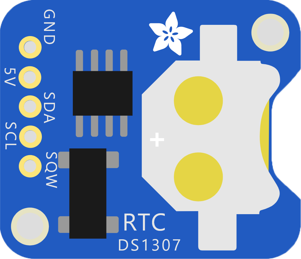
The DS1307 RTC (Real-Time Clock) is a low-power, full binary-coded decimal (BCD) clock/calendar with 56 bytes of NV SRAM. It communicates with a microcontroller via the I2C protocol and is used to keep track of time even when the main device is powered off. The Wokwi Compatible version is designed for easy integration with the Wokwi simulation platform.
Explore Projects Built with DS1307 RTC (Wokwi Compatible)
Arduino UNO Real-Time Clock with DS1307 RTC Module
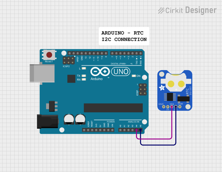
This circuit interfaces an Arduino UNO with a DS1307 Real-Time Clock (RTC) module. The Arduino communicates with the RTC module using the I2C protocol, with connections from A4 to SDA and A5 to SCL.
Arduino UNO with DS1307 RTC Controlled LED Lighting System
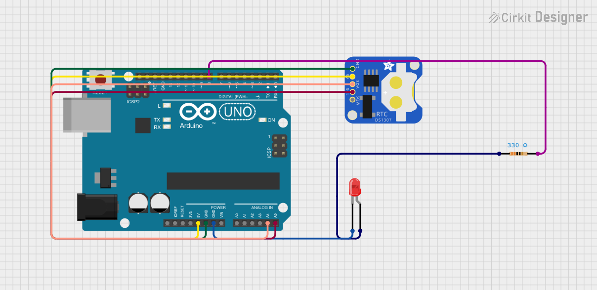
This circuit features an Arduino UNO connected to a DS1307 Real Time Clock (RTC) module for timekeeping and a red LED with a series resistor for indication purposes. The Arduino communicates with the RTC via I2C (using A4 and A5 pins for SDA and SCL, respectively), and controls the LED connected to digital pin D8 through a 330-ohm resistor. The embedded code sets the RTC time, checks the current time, and turns the LED on or off based on the specified time condition (between 11:00 AM and 11:43 AM).
Arduino UNO-Based Real-Time Clock with I2C LCD Display and IO Expansion

This circuit is an Arduino-based real-time clock and display system. It uses an Arduino UNO to interface with a DS1307 RTC module for timekeeping and a 20x4 I2C LCD to display the current time and date. Additionally, a PCF8574 IO Expansion Board is used to extend the I2C bus for additional I/O operations.
Arduino UNO Controlled Servo with DS1307 Real-Time Clock
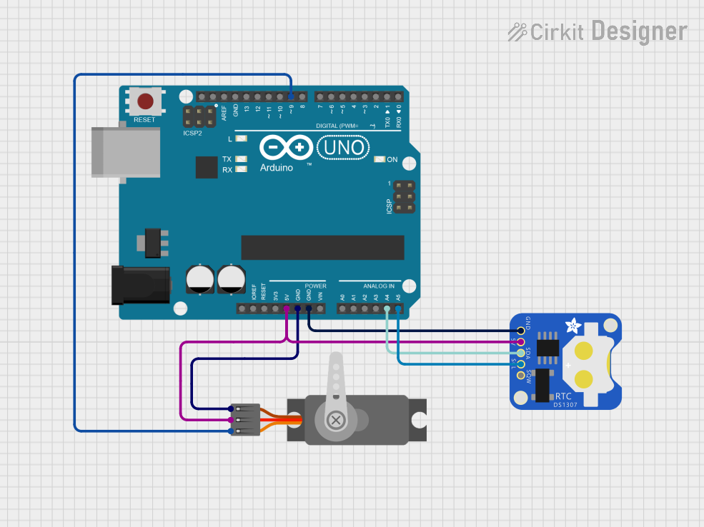
This circuit consists of an Arduino UNO microcontroller connected to a DS1307 Real Time Clock (RTC) module and a servo motor. The RTC module communicates with the Arduino via the I2C protocol using SDA and SCL lines, while the servo is controlled by a PWM signal from the Arduino. The circuit is designed to use the precise timekeeping of the RTC to schedule and execute movements with the servo motor.
Explore Projects Built with DS1307 RTC (Wokwi Compatible)
Arduino UNO Real-Time Clock with DS1307 RTC Module
This circuit interfaces an Arduino UNO with a DS1307 Real-Time Clock (RTC) module. The Arduino communicates with the RTC module using the I2C protocol, with connections from A4 to SDA and A5 to SCL.
Arduino UNO with DS1307 RTC Controlled LED Lighting System
This circuit features an Arduino UNO connected to a DS1307 Real Time Clock (RTC) module for timekeeping and a red LED with a series resistor for indication purposes. The Arduino communicates with the RTC via I2C (using A4 and A5 pins for SDA and SCL, respectively), and controls the LED connected to digital pin D8 through a 330-ohm resistor. The embedded code sets the RTC time, checks the current time, and turns the LED on or off based on the specified time condition (between 11:00 AM and 11:43 AM).
Arduino UNO-Based Real-Time Clock with I2C LCD Display and IO Expansion
This circuit is an Arduino-based real-time clock and display system. It uses an Arduino UNO to interface with a DS1307 RTC module for timekeeping and a 20x4 I2C LCD to display the current time and date. Additionally, a PCF8574 IO Expansion Board is used to extend the I2C bus for additional I/O operations.
Arduino UNO Controlled Servo with DS1307 Real-Time Clock
This circuit consists of an Arduino UNO microcontroller connected to a DS1307 Real Time Clock (RTC) module and a servo motor. The RTC module communicates with the Arduino via the I2C protocol using SDA and SCL lines, while the servo is controlled by a PWM signal from the Arduino. The circuit is designed to use the precise timekeeping of the RTC to schedule and execute movements with the servo motor.
Common Applications and Use Cases
- Time-stamping data logs
- Real-time clocks for embedded systems
- Alarm clocks
- Timers and counters
- Time-based automation systems
Technical Specifications
Key Technical Details
| Parameter | Value |
|---|---|
| Operating Voltage | 4.5V to 5.5V |
| Operating Current | 1.5mA (typical) |
| Timekeeping Current | 500nA (typical) |
| Interface | I2C (2-wire) |
| Clock Accuracy | ±2ppm from 0°C to +40°C |
| NV SRAM | 56 bytes |
| Temperature Range | -40°C to +85°C |
Pin Configuration and Descriptions
| Pin | Name | Description |
|---|---|---|
| 1 | GND | Ground |
| 2 | VCC | Power Supply (4.5V to 5.5V) |
| 3 | SCL | Serial Clock Line (I2C) |
| 4 | SDA | Serial Data Line (I2C) |
| 5 | SQW/OUT | Square Wave/Output Driver (Open Drain) |
| 6 | NC | No Connection |
| 7 | NC | No Connection |
| 8 | VBAT | Battery Backup Input (3V Lithium Cell) |
Usage Instructions
How to Use the Component in a Circuit
- Power Supply: Connect the VCC pin to a 5V power supply and the GND pin to ground.
- I2C Communication: Connect the SCL pin to the I2C clock line of your microcontroller and the SDA pin to the I2C data line.
- Battery Backup: Connect a 3V lithium cell to the VBAT pin to maintain timekeeping when the main power is off.
- Optional Output: The SQW/OUT pin can be used to output a square wave or as a general-purpose output.
Important Considerations and Best Practices
- Pull-up Resistors: Ensure that the I2C lines (SCL and SDA) have pull-up resistors (typically 4.7kΩ) to the VCC.
- Battery Backup: Use a suitable 3V lithium cell for the VBAT pin to ensure continuous timekeeping.
- Decoupling Capacitor: Place a 0.1µF decoupling capacitor close to the VCC pin to filter out noise.
Example Code for Arduino UNO
#include <Wire.h>
#include <RTClib.h>

RTC_DS1307 rtc;

void setup() {
  Serial.begin(9600);
  Wire.begin();
  rtc.begin();

  if (!rtc.isrunning()) {
    Serial.println("RTC is NOT running!");
    // Set the RTC to the date & time this sketch was compiled
    rtc.adjust(DateTime(F(__DATE__), F(__TIME__)));
  }
}

void loop() {
  DateTime now = rtc.now();

  Serial.print(now.year(), DEC);
  Serial.print('/');
  Serial.print(now.month(), DEC);
  Serial.print('/');
  Serial.print(now.day(), DEC);
  Serial.print(" ");
  Serial.print(now.hour(), DEC);
  Serial.print(':');
  Serial.print(now.minute(), DEC);
  Serial.print(':');
  Serial.print(now.second(), DEC);
  Serial.println();

  delay(1000);
}
Troubleshooting and FAQs
Common Issues Users Might Face
- RTC Not Keeping Time: Ensure the battery is properly connected to the VBAT pin.
- I2C Communication Failure: Check the connections and ensure pull-up resistors are in place.
- Incorrect Time: Verify that the RTC is initialized and set correctly.
Solutions and Tips for Troubleshooting
- Check Connections: Ensure all connections are secure and correct.
- Verify Power Supply: Make sure the VCC pin is receiving a stable 5V supply.
- Use Pull-up Resistors: Ensure that the I2C lines have appropriate pull-up resistors.
- Initialize RTC: If the RTC is not running, initialize it using the
rtc.adjust()function.
By following this documentation, users should be able to effectively integrate and utilize the DS1307 RTC in their projects, ensuring accurate timekeeping and reliable performance.