How to Use ESP32-2432S028: Examples, Pinouts, and Specs
Introduction
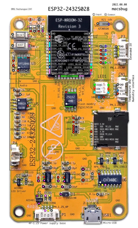
The ESP32-2432S028 is a versatile and powerful microcontroller module designed for IoT and embedded system applications. It features a dual-core processor, integrated Wi-Fi and Bluetooth capabilities, and a 2.8-inch TFT LCD display for user interaction. With its ample GPIO pins and support for various peripherals, the ESP32-2432S028 is ideal for projects requiring wireless communication, graphical interfaces, and real-time processing.
Explore Projects Built with ESP32-2432S028


Explore Projects Built with ESP32-2432S028
Common Applications and Use Cases
- IoT devices and smart home automation
- Industrial control systems
- Wearable technology
- Data logging and monitoring systems
- Wireless communication hubs
- Graphical user interfaces for embedded systems
Technical Specifications
Key Technical Details
| Parameter | Specification |
|---|---|
| Microcontroller | ESP32 dual-core processor |
| Clock Speed | Up to 240 MHz |
| Flash Memory | 4 MB |
| SRAM | 520 KB |
| Wireless Connectivity | Wi-Fi 802.11 b/g/n, Bluetooth 4.2 |
| Display | 2.8-inch TFT LCD, 320x240 resolution |
| GPIO Pins | 28 |
| Operating Voltage | 3.3V |
| Input Voltage Range | 5V (via USB) or 3.3V (via pin) |
| Communication Interfaces | UART, SPI, I2C, PWM, ADC, DAC |
| Power Consumption | ~160 mA (active), ~10 µA (deep sleep) |
| Dimensions | 85mm x 55mm x 12mm |
Pin Configuration and Descriptions
| Pin Number | Pin Name | Description |
|---|---|---|
| 1 | GND | Ground connection |
| 2 | 3V3 | 3.3V power output |
| 3 | VIN | Input voltage (5V via USB or external source) |
| 4 | GPIO0 | General-purpose I/O, boot mode selection |
| 5 | GPIO1 (TX0) | UART0 transmit pin |
| 6 | GPIO3 (RX0) | UART0 receive pin |
| 7 | GPIO4 | General-purpose I/O, supports PWM and ADC |
| 8 | GPIO5 | General-purpose I/O, supports SPI |
| 9 | GPIO12 | General-purpose I/O, supports ADC and touch |
| 10 | GPIO13 | General-purpose I/O, supports ADC and touch |
| 11 | GPIO14 | General-purpose I/O, supports PWM and ADC |
| 12 | GPIO15 | General-purpose I/O, supports PWM and ADC |
| 13 | GPIO16 | General-purpose I/O, supports UART and SPI |
| 14 | GPIO17 | General-purpose I/O, supports UART and SPI |
| 15 | GPIO18 | General-purpose I/O, supports I2C and SPI |
| 16 | GPIO19 | General-purpose I/O, supports I2C and SPI |
| 17 | GPIO21 | General-purpose I/O, supports I2C |
| 18 | GPIO22 | General-purpose I/O, supports I2C |
| 19 | GPIO23 | General-purpose I/O, supports SPI |
| 20 | GPIO25 | General-purpose I/O, supports DAC and ADC |
| 21 | GPIO26 | General-purpose I/O, supports DAC and ADC |
| 22 | GPIO27 | General-purpose I/O, supports ADC and touch |
| 23 | GPIO32 | General-purpose I/O, supports ADC and touch |
| 24 | GPIO33 | General-purpose I/O, supports ADC and touch |
| 25 | GPIO34 | Input-only, supports ADC |
| 26 | GPIO35 | Input-only, supports ADC |
| 27 | GPIO36 | Input-only, supports ADC |
| 28 | GPIO39 | Input-only, supports ADC |
Usage Instructions
How to Use the ESP32-2432S028 in a Circuit
Powering the Module:
- Connect the VIN pin to a 5V power source (e.g., USB or external power supply).
- Alternatively, supply 3.3V directly to the 3V3 pin. Ensure the power source is stable.
Connecting Peripherals:
- Use the GPIO pins to connect sensors, actuators, or other peripherals.
- For communication, use UART, SPI, or I2C interfaces as required by your application.
Programming the ESP32:
- Use the Arduino IDE or ESP-IDF (Espressif IoT Development Framework) to program the module.
- Connect the module to your computer via USB for programming and debugging.
Using the TFT Display:
- The integrated 2.8-inch TFT LCD can be used for graphical output.
- Libraries like
TFT_eSPIorAdafruit_GFXcan simplify display programming.
Important Considerations and Best Practices
- Voltage Levels: Ensure all connected peripherals operate at 3.3V logic levels to avoid damaging the module.
- Deep Sleep Mode: Use deep sleep mode to conserve power in battery-powered applications.
- Boot Mode: To enter programming mode, hold the BOOT button while resetting the module.
- Wi-Fi and Bluetooth: Avoid using both Wi-Fi and Bluetooth simultaneously for high-bandwidth applications, as they share the same radio.
Example Code for Arduino IDE
The following example demonstrates how to display text on the TFT screen and connect to Wi-Fi:
#include <WiFi.h>
#include <TFT_eSPI.h> // Include the TFT library

// Wi-Fi credentials
const char* ssid = "Your_SSID";
const char* password = "Your_PASSWORD";

// Initialize the TFT display
TFT_eSPI tft = TFT_eSPI();

void setup() {
  // Initialize serial communication
  Serial.begin(115200);

  // Initialize the TFT display
  tft.init();
  tft.setRotation(1); // Set display orientation
  tft.fillScreen(TFT_BLACK); // Clear the screen
  tft.setTextColor(TFT_WHITE, TFT_BLACK); // Set text color

  // Display a message on the screen
  tft.setCursor(10, 10);
  tft.setTextSize(2);
  tft.println("Connecting to Wi-Fi...");

  // Connect to Wi-Fi
  WiFi.begin(ssid, password);
  while (WiFi.status() != WL_CONNECTED) {
    delay(500);
    Serial.print(".");
  }

  // Display connection status
  tft.fillScreen(TFT_BLACK);
  tft.setCursor(10, 10);
  tft.println("Wi-Fi Connected!");
  tft.println(WiFi.localIP()); // Display the IP address
}

void loop() {
  // Add your main code here
}
Troubleshooting and FAQs
Common Issues and Solutions
Module Not Powering On:
- Ensure the power supply provides sufficient current (at least 500 mA).
- Check the connections to the VIN or 3V3 pin.
Wi-Fi Connection Fails:
- Verify the SSID and password are correct.
- Check if the Wi-Fi network is within range.
TFT Display Not Working:
- Ensure the display initialization code matches the hardware configuration.
- Verify the connections between the ESP32 and the display.
Programming Errors:
- Ensure the correct board and port are selected in the Arduino IDE.
- Hold the BOOT button while resetting the module to enter programming mode.
FAQs
Can I use 5V peripherals with the ESP32-2432S028?
No, the GPIO pins operate at 3.3V logic levels. Use a level shifter for 5V peripherals.What is the maximum range of the Wi-Fi module?
The Wi-Fi range is approximately 30 meters indoors and 100 meters outdoors, depending on obstacles.How do I update the firmware?
Use the Arduino IDE or ESP-IDF to upload new firmware via USB.Can I use the module without the TFT display?
Yes, the ESP32-2432S028 can function as a standalone microcontroller without using the display.