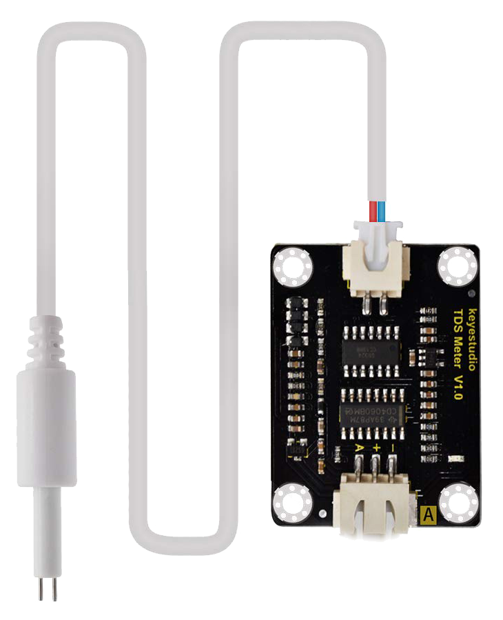
A TDS (Total Dissolved Solids) sensor is an electronic device used to measure the concentration of dissolved solids in a liquid. These dissolved solids include minerals, salts, and organic matter, which affect the conductivity of the liquid. The sensor provides a TDS value in parts per million (ppm), which is a key indicator of water quality.
Explore Projects Built with TDs sensor
Use Cirkit Designer to design, explore, and prototype these projects online. Some projects support real-time simulation. Click "Open Project" to start designing instantly!
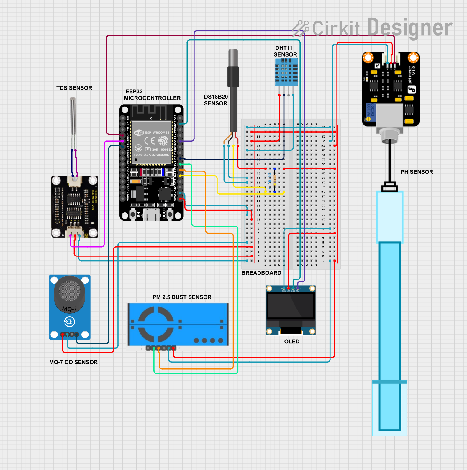
This circuit is an environmental monitoring system using an ESP32 microcontroller to collect data from various sensors, including temperature, humidity, air quality, pH, and TDS sensors. The collected data is displayed on an OLED screen, sent to ThingSpeak for remote monitoring, and email alerts are sent if critical thresholds are exceeded.
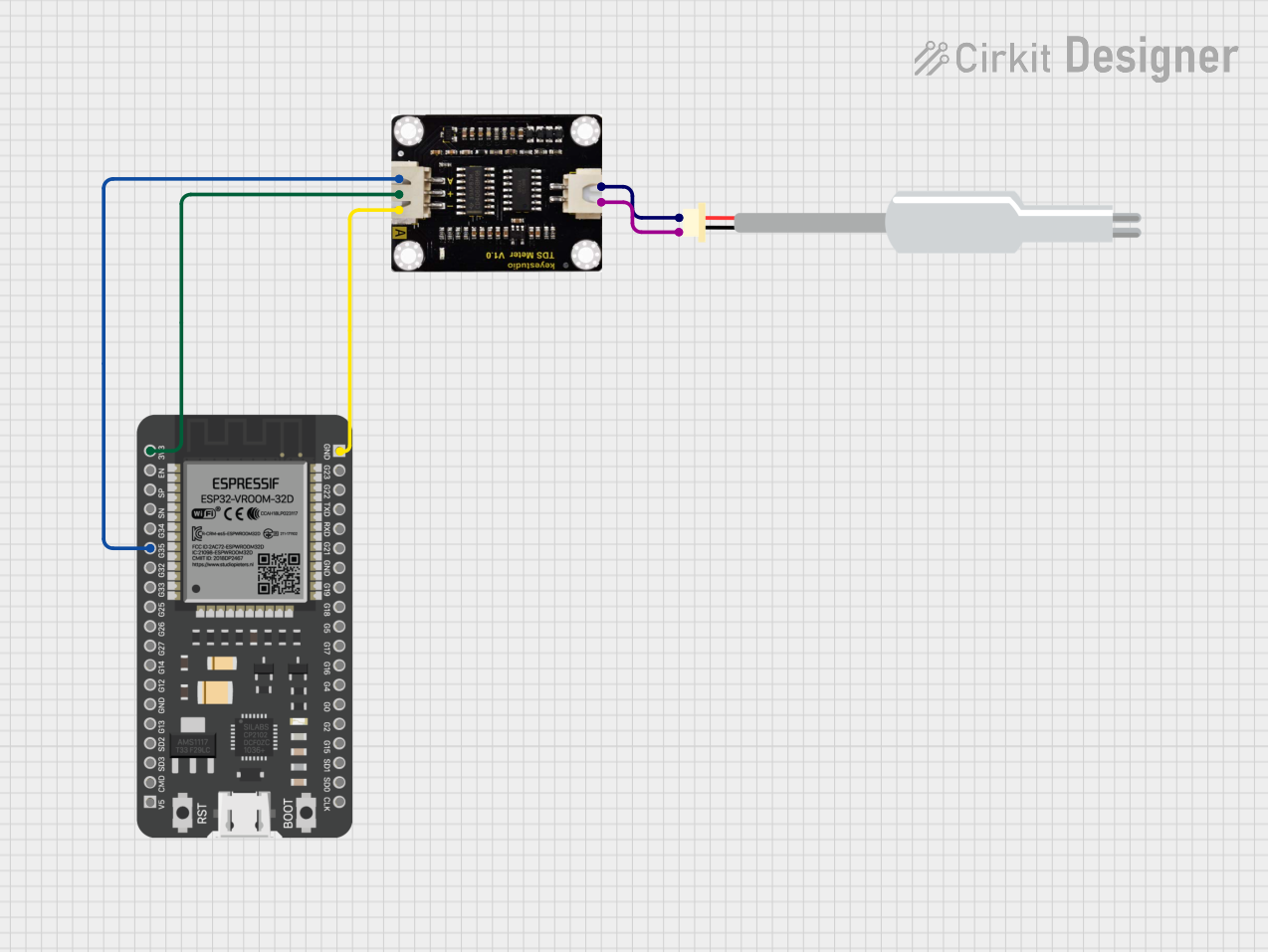
This circuit connects a TDS (Total Dissolved Solids) sensor to an ESP32 microcontroller. The TDS sensor's power is supplied by the ESP32's 3.3V and ground pins, and its analog output is connected to GPIO 35 of the ESP32 for measurement. The purpose of this circuit is to enable the ESP32 to read the TDS level of a solution, which is commonly used in water quality testing.
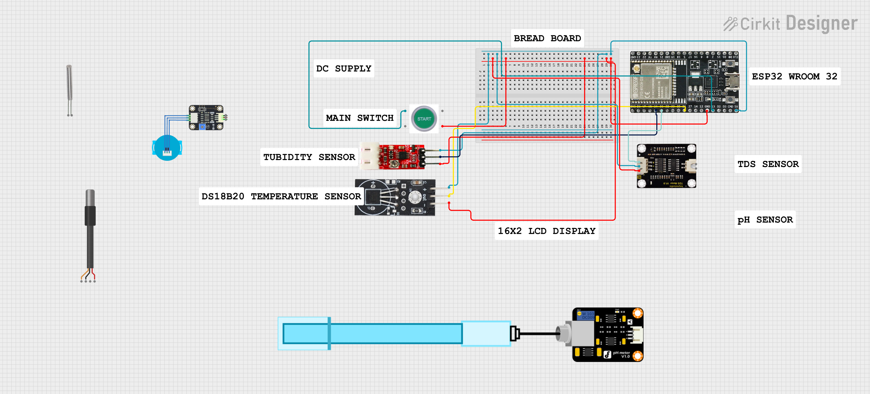
This circuit is a water quality monitoring system that uses an ESP32 microcontroller to measure TDS, pH, temperature, and turbidity of water. The system includes sensors for each parameter and a start switch, with data being displayed on a 16x2 I2C LCD and logged via serial communication.
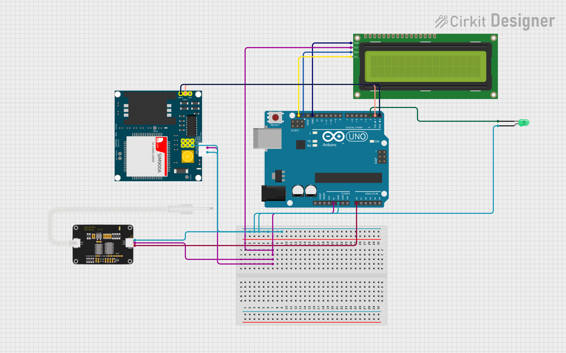
This circuit is a water quality monitoring system using an Arduino Uno, which reads TDS values from a TDS sensor and displays the results on a 16x2 I2C LCD. A green LED indicates good water quality, while a SIM900A module sends an SMS alert if the water quality is poor.
Water quality monitoring in aquariums, hydroponics, and swimming pools
Drinking water purification systems
Industrial water treatment processes
Environmental monitoring of rivers, lakes, and groundwater
Agricultural irrigation systems
Technical Specifications
Below are the key technical details and pin configuration for a typical TDS sensor module:
Key Technical Details
Parameter
Value
Operating Voltage
3.3V - 5.0V
Operating Current
3-6 mA
Measurement Range
0 - 1000 ppm
Accuracy
±10% (25°C calibration)
Output Signal
Analog voltage (0-2.3V typical)
Temperature Compensation
Supported (via external probe)
Operating Temperature
0°C - 60°C
Pin Configuration
Pin Name
Description
VCC
Power supply input (3.3V - 5.0V)
GND
Ground connection
AOUT
Analog output signal proportional to TDS value
TEMP
Optional connection for temperature probe input
Usage Instructions
How to Use the TDS Sensor in a Circuit
Power the Sensor: Connect the VCC pin to a 3.3V or 5.0V power source and the GND pin to the ground.
Connect the Analog Output: Connect the AOUT pin to an analog input pin on your microcontroller (e.g., Arduino).
Optional Temperature Compensation: If your sensor supports temperature compensation, connect the external temperature probe to the TEMP pin.
Calibrate the Sensor: Use a known TDS solution to calibrate the sensor for accurate readings. Adjust the calibration potentiometer on the module if available.
Read the Output: The sensor outputs an analog voltage proportional to the TDS value. Use an ADC (Analog-to-Digital Converter) to read and process the signal.
Important Considerations and Best Practices
Avoid Corrosion: Do not leave the sensor submerged in water for extended periods to prevent electrode corrosion.
Temperature Effects: Use temperature compensation for accurate readings in varying temperature conditions.
Clean the Sensor: Rinse the sensor with distilled water after each use to prevent residue buildup.
Avoid High TDS Levels: The sensor is designed for TDS levels up to 1000 ppm. Exceeding this range may damage the sensor or produce inaccurate readings.
Example: Connecting to an Arduino UNO
Below is an example of how to connect and use a TDS sensor with an Arduino UNO:
Circuit Diagram
Connect VCC to the Arduino's 5V pin.
Connect GND to the Arduino's GND pin.
Connect AOUT to the Arduino's A0 pin.
Arduino Code
// TDS Sensor Example Code for Arduino UNO
// Reads the analog output from the TDS sensor and converts it to a TDS value.

const int TDS_PIN = A0; // Analog pin connected to the TDS sensor's AOUT
float voltage;          // Variable to store the sensor's output voltage
float tdsValue;         // Variable to store the calculated TDS value

void setup() {
  Serial.begin(9600); // Initialize serial communication for debugging
  pinMode(TDS_PIN, INPUT); // Set the TDS pin as an input
}

void loop() {
  int sensorValue = analogRead(TDS_PIN); // Read the analog value from the sensor
  voltage = sensorValue * (5.0 / 1023.0); // Convert ADC value to voltage
  tdsValue = (voltage * 1000) / 2.3; // Convert voltage to TDS (ppm)

  // Print the TDS value to the Serial Monitor
  Serial.print("TDS Value: ");
  Serial.print(tdsValue);
  Serial.println(" ppm");

  delay(1000); // Wait for 1 second before the next reading
}
Troubleshooting and FAQs
Common Issues and Solutions
Inaccurate Readings
Cause: Sensor not calibrated.
Solution: Calibrate the sensor using a standard TDS solution.
No Output Signal
Cause: Incorrect wiring or insufficient power supply.
Solution: Verify all connections and ensure the power supply matches the sensor's requirements.
Fluctuating Readings
Cause: Electrical noise or unstable water conditions.
Solution: Use a capacitor across the power supply pins to reduce noise. Ensure the water sample is stable.
Sensor Corrosion
Cause: Prolonged exposure to water.
Solution: Limit the sensor's immersion time and clean it after use.
FAQs
Q: Can the TDS sensor measure salinity?
A: While the TDS sensor measures dissolved solids, it is not specifically designed for salinity measurement. However, it can provide an approximate salinity value in ppm.
Q: How often should I calibrate the sensor?
A: Calibration is recommended every 2-3 months or whenever you notice inaccurate readings.
Q: Can I use the TDS sensor in hot water?
A: The sensor operates within a temperature range of 0°C to 60°C. Avoid using it in water outside this range to prevent damage.
Q: Is the TDS sensor waterproof?
A: The sensor probe is waterproof, but the module is not. Ensure the module remains dry during operation.

 Open Project in Cirkit Designer