
How to Use PN00218-CYT19 Cytron Dual Channel 20A DC Motor Driver MDD20A: Examples, Pinouts, and Specs
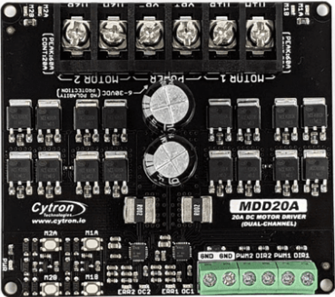
 Design with PN00218-CYT19 Cytron Dual Channel 20A DC Motor Driver MDD20A in Cirkit Designer
Introduction
The PN00218-CYT19 Cytron Dual Channel 20A DC Motor Driver MDD20A is a high-performance motor driver designed to control two DC motors independently. With a maximum continuous current rating of 20A per channel, this motor driver is ideal for robotics, automation, and other applications requiring precise motor control. Its robust design ensures reliable operation, even under demanding conditions.
Explore Projects Built with PN00218-CYT19 Cytron Dual Channel 20A DC Motor Driver MDD20A
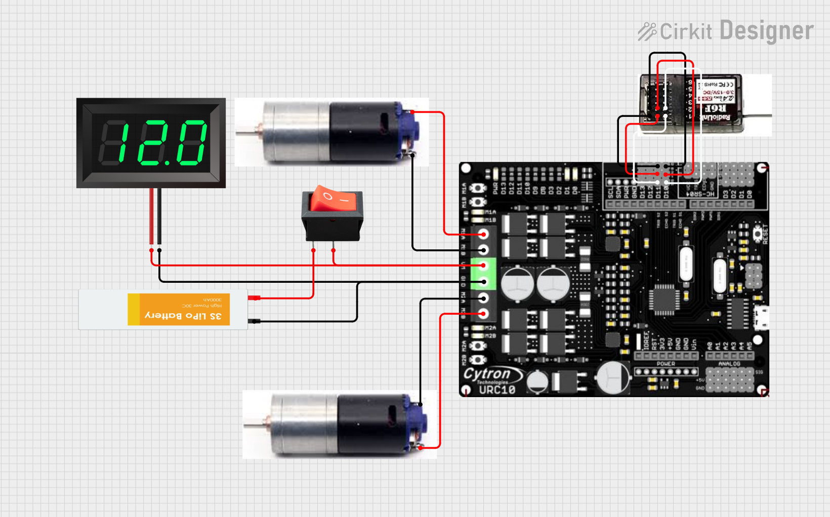 Open Project in Cirkit Designer
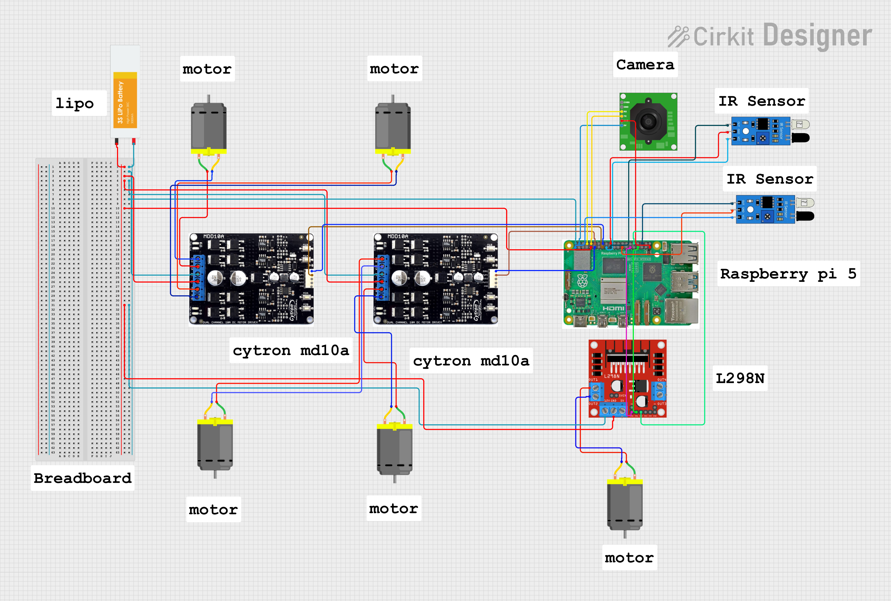 Open Project in Cirkit Designer
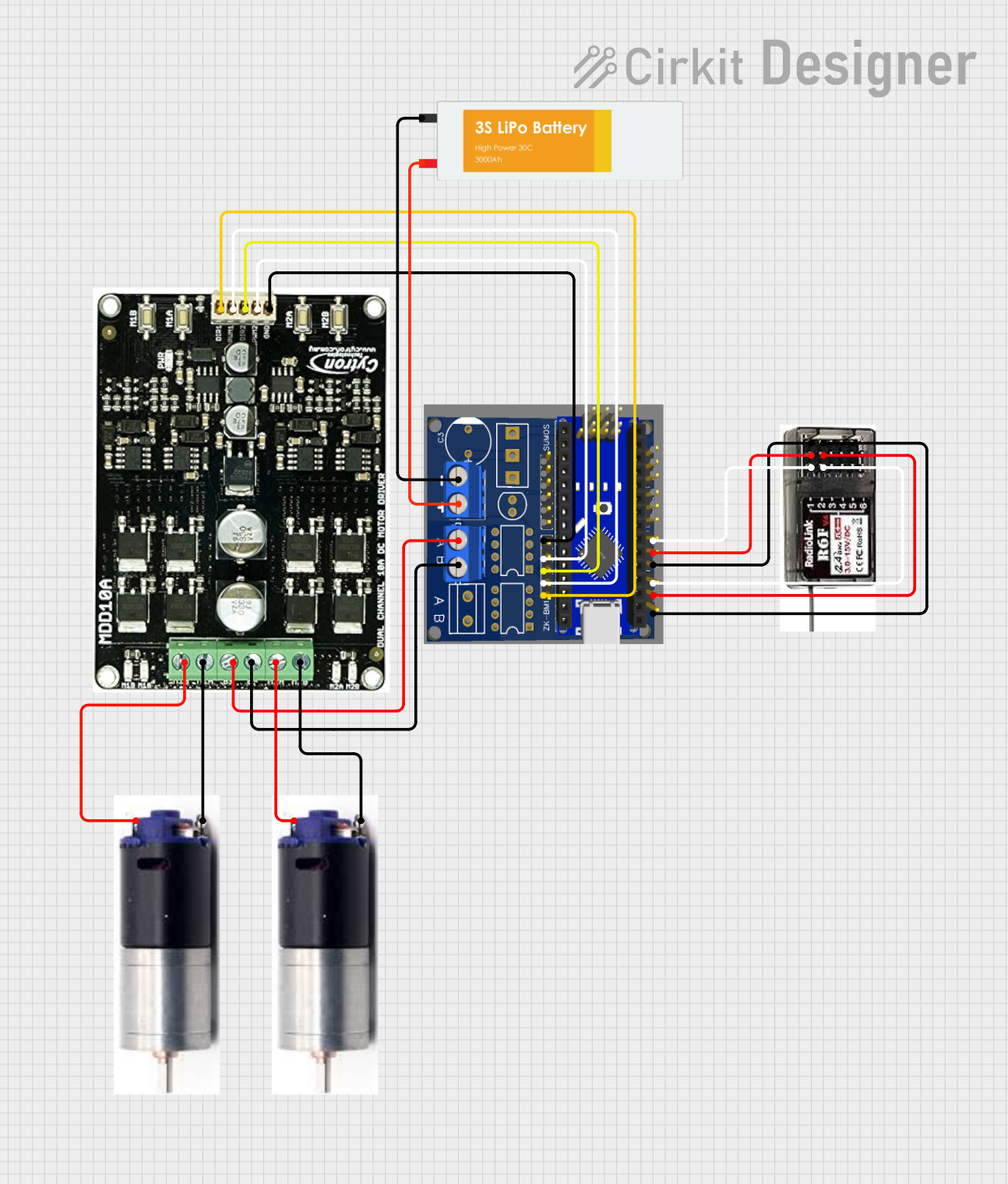 Open Project in Cirkit Designer
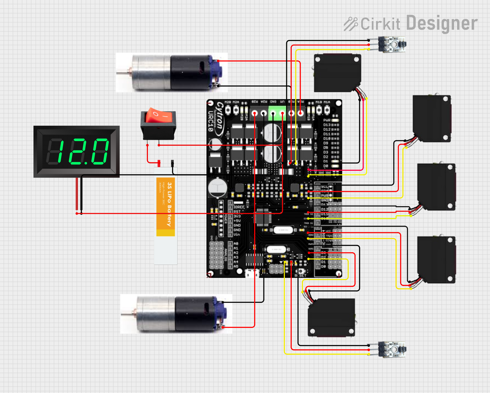 Open Project in Cirkit Designer
Explore Projects Built with PN00218-CYT19 Cytron Dual Channel 20A DC Motor Driver MDD20A
Open Project in Cirkit DesignerOpen Project in Cirkit DesignerOpen Project in Cirkit DesignerOpen Project in Cirkit DesignerCommon Applications
- Robotics (e.g., mobile robots, robotic arms)
- Automated guided vehicles (AGVs)
- Conveyor belt systems
- Electric wheelchairs
- General-purpose DC motor control in industrial and hobbyist projects
Technical Specifications
The following table outlines the key technical specifications of the PN00218-CYT19 motor driver:
| Parameter | Specification |
|---|---|
| Manufacturer | Cytron |
| Part ID | PN00218-CYT19 |
| Motor Channels | 2 |
| Maximum Continuous Current | 20A per channel |
| Peak Current | 30A per channel (for 10 seconds) |
| Operating Voltage Range | 7V to 30V DC |
| Control Signal Voltage | 3.3V or 5V logic compatible |
| PWM Frequency | Up to 20 kHz |
| Protection Features | Overcurrent, overtemperature, and reverse polarity |
| Dimensions | 84mm x 62mm x 25mm |
| Weight | 80g |
Pin Configuration and Descriptions
The motor driver has several key connectors and pins for power, motor outputs, and control signals. The table below describes the pin configuration:
Power and Motor Output Pins
| Pin Name | Description |
|---|---|
| VM | Motor power supply input (7V to 30V DC) |
| GND | Ground connection |
| M1A, M1B | Motor 1 output terminals |
| M2A, M2B | Motor 2 output terminals |
Control Signal Pins
| Pin Name | Description |
|---|---|
| DIR1 | Direction control for Motor 1 |
| PWM1 | PWM speed control for Motor 1 |
| DIR2 | Direction control for Motor 2 |
| PWM2 | PWM speed control for Motor 2 |
| GND | Ground reference for control signals |
Usage Instructions
How to Use the Component in a Circuit
- Power Connection: Connect the VM pin to a DC power source (7V to 30V) and the GND pin to the ground of the power source.
- Motor Connection: Connect the DC motors to the M1A/M1B and M2A/M2B terminals. Ensure proper polarity for desired motor rotation.
- Control Signal Connection: Use a microcontroller (e.g., Arduino UNO) to send PWM and direction signals to the DIR1, PWM1, DIR2, and PWM2 pins. Ensure the control signal ground is connected to the motor driver’s GND.
- Logic Voltage Compatibility: The motor driver supports both 3.3V and 5V logic levels, making it compatible with most microcontrollers.
Important Considerations and Best Practices
- Heat Dissipation: The motor driver may heat up during operation. Use a heatsink or active cooling if operating near the maximum current rating.
- Power Supply: Ensure the power supply can provide sufficient current for both motors.
- PWM Frequency: Use a PWM frequency of up to 20 kHz for optimal performance.
- Protection Features: The motor driver includes built-in protection for overcurrent, overtemperature, and reverse polarity. However, avoid prolonged operation near the limits to ensure longevity.
Example Code for Arduino UNO
Below is an example code snippet to control two DC motors using the PN00218-CYT19 motor driver with an Arduino UNO:
// Define control pins for Motor 1
#define DIR1_PIN 7  // Direction pin for Motor 1
#define PWM1_PIN 6  // PWM pin for Motor 1

// Define control pins for Motor 2
#define DIR2_PIN 4  // Direction pin for Motor 2
#define PWM2_PIN 5  // PWM pin for Motor 2

void setup() {
  // Set motor control pins as outputs
  pinMode(DIR1_PIN, OUTPUT);
  pinMode(PWM1_PIN, OUTPUT);
  pinMode(DIR2_PIN, OUTPUT);
  pinMode(PWM2_PIN, OUTPUT);
}

void loop() {
  // Example: Rotate Motor 1 forward at 50% speed
  digitalWrite(DIR1_PIN, HIGH);  // Set direction forward
  analogWrite(PWM1_PIN, 128);   // Set speed (128 = 50% duty cycle)

  // Example: Rotate Motor 2 backward at 75% speed
  digitalWrite(DIR2_PIN, LOW);  // Set direction backward
  analogWrite(PWM2_PIN, 192);  // Set speed (192 = 75% duty cycle)

  delay(5000);  // Run motors for 5 seconds

  // Stop both motors
  analogWrite(PWM1_PIN, 0);  // Stop Motor 1
  analogWrite(PWM2_PIN, 0);  // Stop Motor 2

  delay(2000);  // Wait for 2 seconds before repeating
}
Troubleshooting and FAQs
Common Issues and Solutions
Motors Not Spinning
- Cause: Incorrect wiring or insufficient power supply.
- Solution: Double-check all connections and ensure the power supply meets the voltage and current requirements.
Overheating
- Cause: Prolonged operation at high current or insufficient cooling.
- Solution: Add a heatsink or active cooling to the motor driver.
Erratic Motor Behavior
- Cause: Noise in the control signals or power supply.
- Solution: Use decoupling capacitors on the power supply and ensure proper grounding.
Motor Driver Not Responding
- Cause: Incorrect logic voltage levels or damaged components.
- Solution: Verify the control signal voltage (3.3V or 5V) and inspect the motor driver for physical damage.
FAQs
Can I use this motor driver with a 12V battery? Yes, the motor driver supports a voltage range of 7V to 30V, so a 12V battery is suitable.
What happens if the motor stalls? The motor driver includes overcurrent protection, which will limit the current to prevent damage.
Can I control brushless motors with this driver? No, this motor driver is designed for brushed DC motors only.
Is it compatible with Raspberry Pi? Yes, the motor driver is compatible with Raspberry Pi, as it supports 3.3V logic levels.