
How to Use ponte h l298n Mini: Examples, Pinouts, and Specs
 Design with ponte h l298n Mini in Cirkit Designer
Introduction
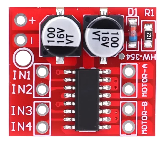
The Ponte H L298N Mini is a compact dual H-bridge motor driver module designed to control DC motors and stepper motors. It is based on the L298N IC, which allows for bidirectional control of two motors simultaneously. This module is widely used in robotics, automation, and other motor control applications due to its small size, ease of use, and ability to handle moderate power loads.
Explore Projects Built with ponte h l298n Mini
 Open Project in Cirkit Designer
 Open Project in Cirkit Designer
 Open Project in Cirkit Designer
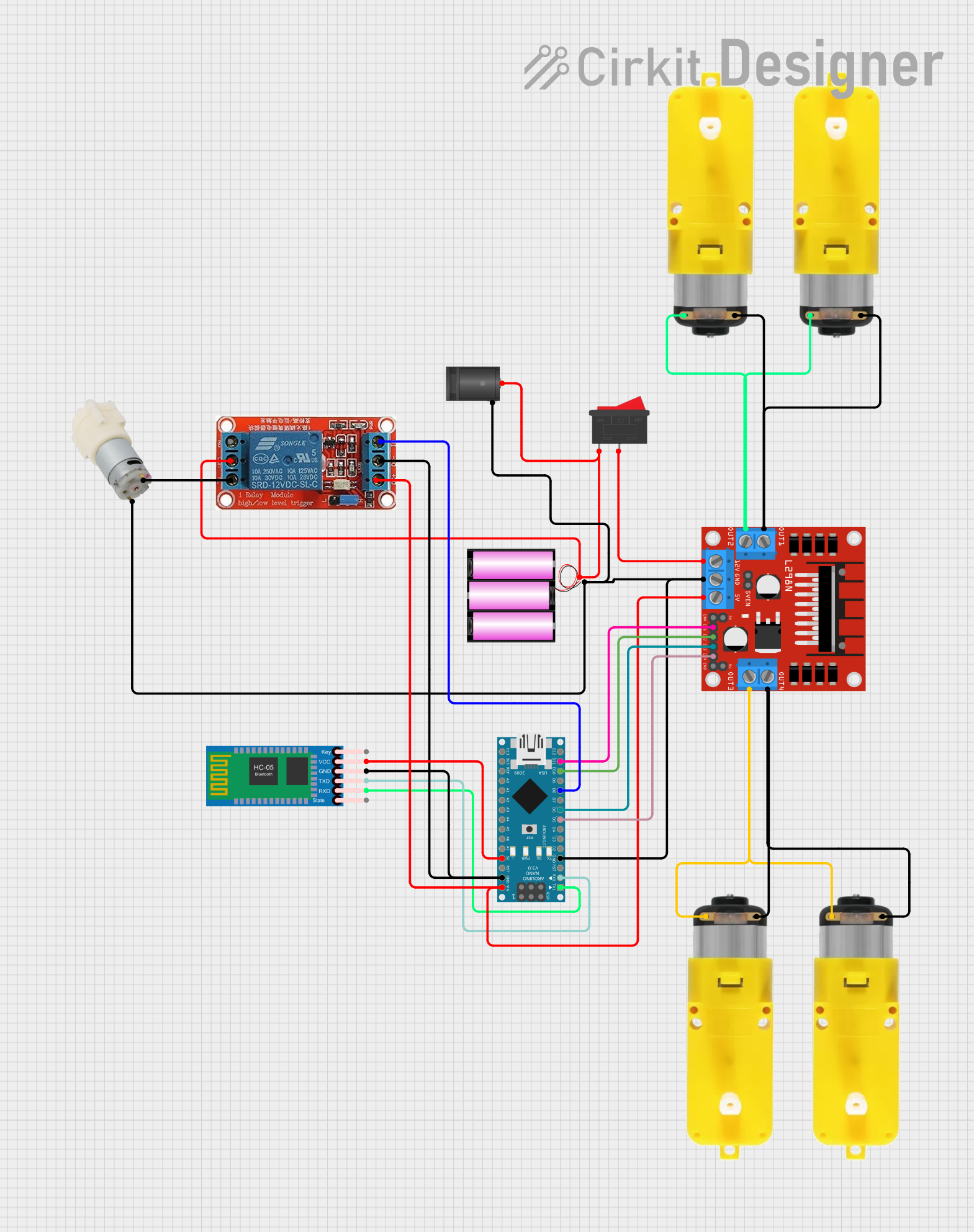 Open Project in Cirkit Designer
Explore Projects Built with ponte h l298n Mini
Open Project in Cirkit DesignerOpen Project in Cirkit DesignerOpen Project in Cirkit DesignerOpen Project in Cirkit DesignerCommon Applications and Use Cases
- Driving DC motors in robotics projects
- Controlling stepper motors in CNC machines or 3D printers
- Motorized vehicles, such as RC cars or robotic arms
- Automation systems requiring precise motor control
Technical Specifications
- Operating Voltage: 5V to 35V
- Output Current: Up to 2A per channel (continuous)
- Peak Current: 3A per channel (short duration)
- Logic Voltage: 5V
- Control Logic Levels: 0V (LOW) and 5V (HIGH)
- Power Dissipation: 25W (with proper heat sinking)
- Number of Channels: 2 (can control two motors independently)
- Dimensions: Approximately 43mm x 43mm x 27mm
Pin Configuration and Descriptions
The L298N Mini module has several pins for motor control and power input. Below is the pinout:
| Pin Name | Description |
|---|---|
VCC |
Power supply for the motors (5V to 35V). |
GND |
Ground connection. |
5V |
Logic voltage output (can power external logic circuits if VCC > 7V). |
IN1 |
Input signal for Motor A (controls direction). |
IN2 |
Input signal for Motor A (controls direction). |
IN3 |
Input signal for Motor B (controls direction). |
IN4 |
Input signal for Motor B (controls direction). |
ENA |
Enable pin for Motor A (PWM input for speed control). |
ENB |
Enable pin for Motor B (PWM input for speed control). |
OUT1 |
Output terminal for Motor A. |
OUT2 |
Output terminal for Motor A. |
OUT3 |
Output terminal for Motor B. |
OUT4 |
Output terminal for Motor B. |
Usage Instructions
How to Use the Component in a Circuit
Power Connections:
- Connect the
VCCpin to the motor power supply (5V to 35V). - Connect the
GNDpin to the ground of the power supply and the microcontroller. - If the motor power supply is greater than 7V, the
5Vpin can be used to power the logic circuit.
- Connect the
Motor Connections:
- Connect the motor terminals to the
OUT1andOUT2pins for Motor A, andOUT3andOUT4pins for Motor B.
- Connect the motor terminals to the
Control Connections:
- Connect the
IN1andIN2pins to the microcontroller's GPIO pins to control Motor A's direction. - Connect the
IN3andIN4pins to the microcontroller's GPIO pins to control Motor B's direction. - Use the
ENAandENBpins for PWM signals to control the speed of Motor A and Motor B, respectively.
- Connect the
Logic Voltage:
- Ensure the logic voltage levels (0V and 5V) are compatible with the microcontroller.
Important Considerations and Best Practices
- Use a heat sink on the L298N IC if driving motors with high current to prevent overheating.
- Add decoupling capacitors near the power supply pins to reduce noise and voltage spikes.
- Avoid exceeding the maximum current and voltage ratings to prevent damage to the module.
- Use flyback diodes across the motor terminals if not already integrated into the module to protect against back EMF.
Example Code for Arduino UNO
Below is an example of how to control a DC motor using the L298N Mini module with an Arduino UNO:
// Define motor control pins
const int IN1 = 9;  // Motor A direction pin 1
const int IN2 = 8;  // Motor A direction pin 2
const int ENA = 10; // Motor A speed control (PWM)

// Setup function to initialize pins
void setup() {
  pinMode(IN1, OUTPUT); // Set IN1 as output
  pinMode(IN2, OUTPUT); // Set IN2 as output
  pinMode(ENA, OUTPUT); // Set ENA as output
}

// Loop function to control motor
void loop() {
  // Rotate motor forward
  digitalWrite(IN1, HIGH); // Set IN1 HIGH
  digitalWrite(IN2, LOW);  // Set IN2 LOW
  analogWrite(ENA, 150);   // Set speed to 150 (range: 0-255)
  delay(2000);             // Run for 2 seconds

  // Stop motor
  digitalWrite(IN1, LOW);  // Set IN1 LOW
  digitalWrite(IN2, LOW);  // Set IN2 LOW
  analogWrite(ENA, 0);     // Set speed to 0
  delay(1000);             // Wait for 1 second

  // Rotate motor backward
  digitalWrite(IN1, LOW);  // Set IN1 LOW
  digitalWrite(IN2, HIGH); // Set IN2 HIGH
  analogWrite(ENA, 200);   // Set speed to 200 (range: 0-255)
  delay(2000);             // Run for 2 seconds

  // Stop motor
  digitalWrite(IN1, LOW);  // Set IN1 LOW
  digitalWrite(IN2, LOW);  // Set IN2 LOW
  analogWrite(ENA, 0);     // Set speed to 0
  delay(1000);             // Wait for 1 second
}
Troubleshooting and FAQs
Common Issues Users Might Face
Motor Not Spinning:
- Check the power supply voltage and ensure it is within the operating range.
- Verify the connections to the motor and the control pins.
- Ensure the
ENAorENBpins are receiving a valid PWM signal.
Overheating:
- Ensure the module has adequate heat dissipation (use a heat sink if necessary).
- Avoid exceeding the maximum current rating of 2A per channel.
Erratic Motor Behavior:
- Check for loose or incorrect wiring.
- Add decoupling capacitors to the power supply to reduce noise.
No Output on Motor Terminals:
- Verify that the input control signals (
IN1,IN2, etc.) are correctly configured. - Ensure the enable pins (
ENA,ENB) are not left floating.
- Verify that the input control signals (
Solutions and Tips for Troubleshooting
- Use a multimeter to check voltage levels at the input and output pins.
- Test the module with a lower voltage and current motor to ensure basic functionality.
- Double-check the Arduino code for errors in pin assignments or logic.
By following this documentation, users can effectively integrate the Ponte H L298N Mini module into their projects for reliable motor control.