How to Use 2P Breaker: Examples, Pinouts, and Specs
Introduction
A 2-pole circuit breaker (commonly referred to as a 2P breaker) is an essential safety device designed to protect electrical circuits from overloads and short circuits. It is capable of disconnecting power in two separate phases simultaneously, ensuring the safety of both the electrical system and connected devices.
2P breakers are widely used in residential, commercial, and industrial applications where two-phase power systems are present. They are particularly useful in protecting high-power appliances, HVAC systems, and other equipment that requires two-phase power.
Explore Projects Built with 2P Breaker
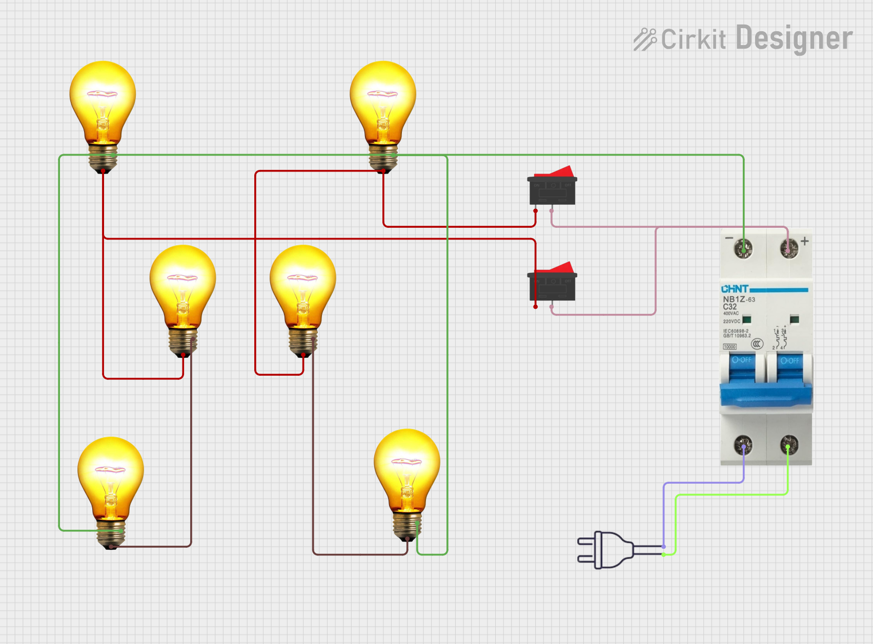

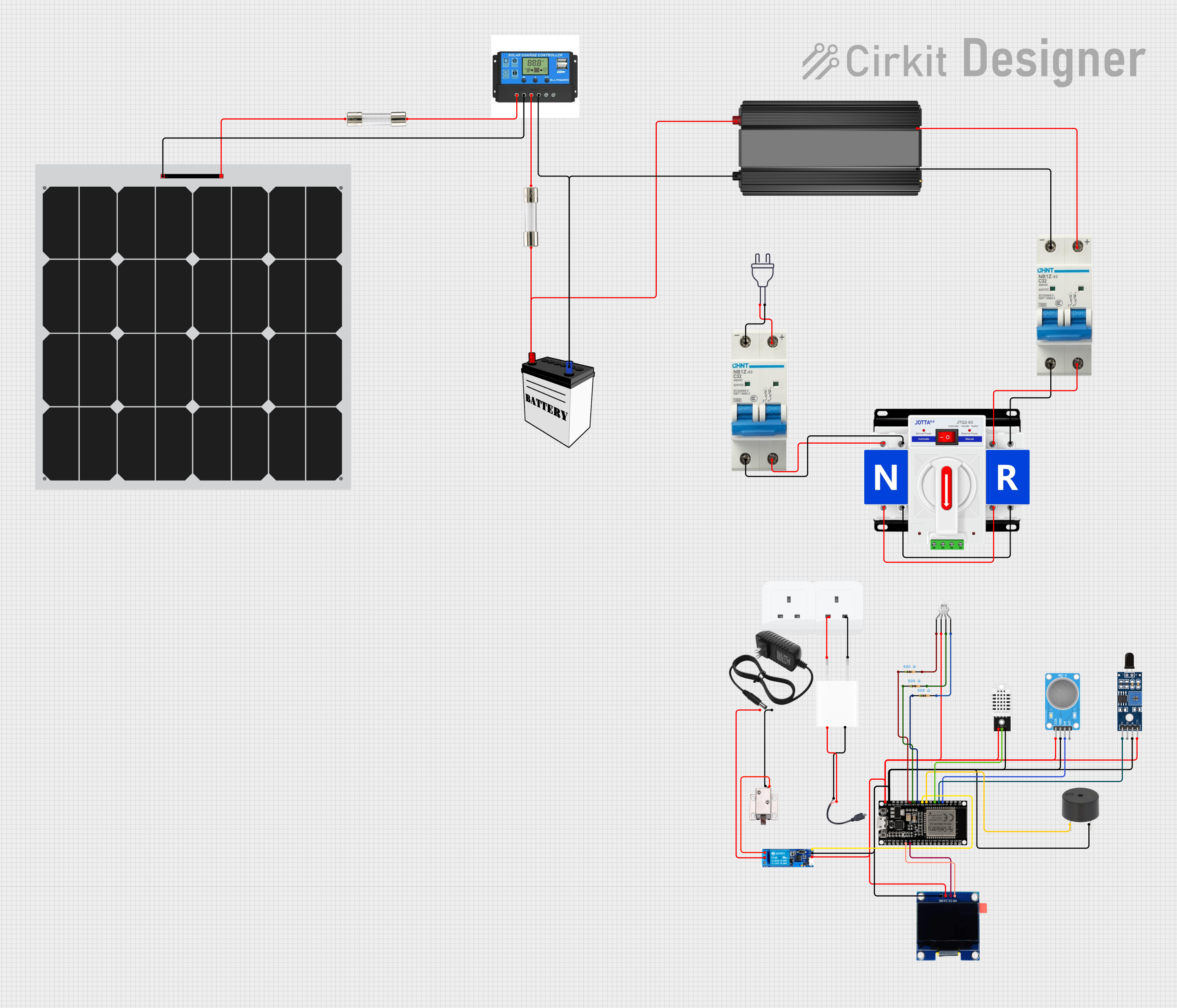

Explore Projects Built with 2P Breaker
Technical Specifications
Below are the key technical details of a typical 2P breaker:
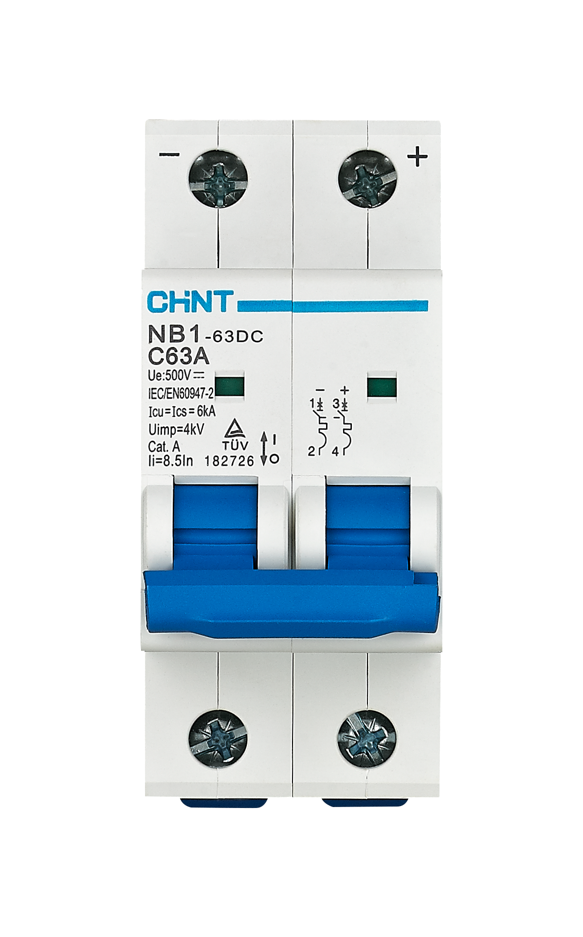
- Rated Voltage: 120/240V AC or 240V AC (varies by model)
- Rated Current: 10A, 20A, 30A, 50A, or higher (depending on the application)
- Interrupting Capacity: 10kA to 65kA (varies by model)
- Number of Poles: 2
- Trip Mechanism: Thermal-magnetic
- Mounting Type: DIN rail or panel-mounted
- Operating Temperature: -20°C to 70°C
- Standards Compliance: UL 489, IEC 60947-2
Pin Configuration and Descriptions
The 2P breaker has the following terminals:
| Terminal Name | Description |
|---|---|
| Line 1 (L1) | Input terminal for the first phase of the power supply. |
| Line 2 (L2) | Input terminal for the second phase of the power supply. |
| Load 1 (T1) | Output terminal for the first phase, connected to the load. |
| Load 2 (T2) | Output terminal for the second phase, connected to the load. |
Usage Instructions
How to Use the 2P Breaker in a Circuit
- Determine the Load Requirements: Ensure the breaker’s rated current and voltage match the requirements of your circuit and connected devices.
- Turn Off Power: Before installation, disconnect the main power supply to avoid electrical hazards.
- Connect the Input Terminals:
- Connect the first phase of the power supply to the Line 1 (L1) terminal.
- Connect the second phase of the power supply to the Line 2 (L2) terminal.
- Connect the Output Terminals:
- Connect the load’s first phase to the Load 1 (T1) terminal.
- Connect the load’s second phase to the Load 2 (T2) terminal.
- Secure the Breaker: Mount the breaker onto a DIN rail or panel as per the manufacturer’s instructions.
- Test the Circuit: After installation, restore power and test the breaker by simulating an overload or short circuit to ensure proper operation.
Important Considerations and Best Practices
- Always select a breaker with a current rating slightly higher than the maximum expected load current.
- Ensure proper torque is applied to terminal screws to avoid loose connections.
- Regularly inspect the breaker for signs of wear, overheating, or damage.
- Do not exceed the breaker’s interrupting capacity, as this may result in failure during a fault condition.
- For three-phase systems, use a 3-pole breaker instead of a 2P breaker.
Example: Connecting a 2P Breaker to an Arduino-Controlled Circuit
While 2P breakers are not directly connected to microcontrollers like Arduino, they can be used to protect circuits powered by relays or motor drivers controlled by an Arduino. Below is an example of how an Arduino can control a relay to manage a load protected by a 2P breaker:
// Example: Arduino controlling a relay for a load protected by a 2P breaker
const int relayPin = 7; // Pin connected to the relay module

void setup() {
  pinMode(relayPin, OUTPUT); // Set relay pin as output
  digitalWrite(relayPin, LOW); // Ensure relay is off at startup
}

void loop() {
  // Turn on the relay to power the load
  digitalWrite(relayPin, HIGH);
  delay(5000); // Keep the load powered for 5 seconds

  // Turn off the relay to disconnect the load
  digitalWrite(relayPin, LOW);
  delay(5000); // Wait for 5 seconds before repeating
}
Note: Ensure the relay module and load are rated for the voltage and current of the circuit protected by the 2P breaker.
Troubleshooting and FAQs
Common Issues and Solutions
Breaker Trips Frequently:
- Cause: Overloaded circuit or short circuit.
- Solution: Reduce the load on the circuit or inspect for wiring faults.
Breaker Does Not Trip During a Fault:
- Cause: Faulty breaker or incorrect installation.
- Solution: Replace the breaker and verify proper wiring.
Overheating of Terminals:
- Cause: Loose connections or undersized wires.
- Solution: Tighten terminal screws and use wires of appropriate gauge.
Breaker Fails to Reset:
- Cause: Persistent fault in the circuit.
- Solution: Identify and resolve the fault before attempting to reset the breaker.
FAQs
Q: Can a 2P breaker be used in single-phase systems?
A: Yes, but only one pole will be active. It is generally more efficient to use a single-pole breaker for single-phase systems.Q: How do I know if my breaker is compatible with my panel?
A: Check the breaker’s specifications and ensure it matches the panel’s voltage, current, and mounting type.Q: Can I use a 2P breaker for DC circuits?
A: Some 2P breakers are rated for DC use, but you must verify the specifications to ensure compatibility.Q: How often should I test my breaker?
A: It is recommended to test the breaker at least once a year to ensure proper functionality.