How to Use MPU6050: Examples, Pinouts, and Specs
Introduction
The MPU6050 is a 6-axis motion tracking device manufactured by InvenSense. It integrates a 3-axis gyroscope and a 3-axis accelerometer on a single chip, enabling precise measurement of angular velocity and acceleration in three-dimensional space. This compact and versatile sensor is widely used in applications requiring motion tracking, orientation detection, and stabilization.
Explore Projects Built with MPU6050

Explore Projects Built with MPU6050
Common Applications and Use Cases
- Robotics: Motion tracking and stabilization
- Drones: Flight control and orientation sensing
- Wearable devices: Step counting and activity monitoring
- Gaming: Gesture recognition and motion control
- Industrial equipment: Vibration analysis and monitoring
Technical Specifications
The following table outlines the key technical details of the MPU6050:
| Parameter | Value |
|---|---|
| Manufacturer | InvenSense |
| Part ID | MPU-6050 |
| Supply Voltage (VDD) | 2.375V to 3.46V |
| Logic Voltage (VDDIO) | 1.8V to VDD |
| Gyroscope Range | ±250, ±500, ±1000, ±2000 °/s |
| Accelerometer Range | ±2g, ±4g, ±8g, ±16g |
| Communication Interface | I2C (up to 400kHz) or SPI |
| Operating Temperature | -40°C to +85°C |
| Package | 4x4x0.9 mm QFN |
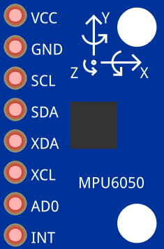
Pin Configuration and Descriptions
The MPU6050 has 24 pins, but the most commonly used pins for basic operation are listed below:
| Pin Name | Pin Number | Description |
|---|---|---|
| VDD | 1 | Power supply input (2.375V to 3.46V) |
| VDDIO | 2 | Logic voltage input (1.8V to VDD) |
| GND | 3 | Ground |
| SCL | 6 | I2C clock input |
| SDA | 7 | I2C data input/output |
| AD0 | 8 | I2C address select (0 or 1) |
| INT | 12 | Interrupt output |
| FSYNC | 14 | Frame synchronization input |
For a complete pinout, refer to the official datasheet.
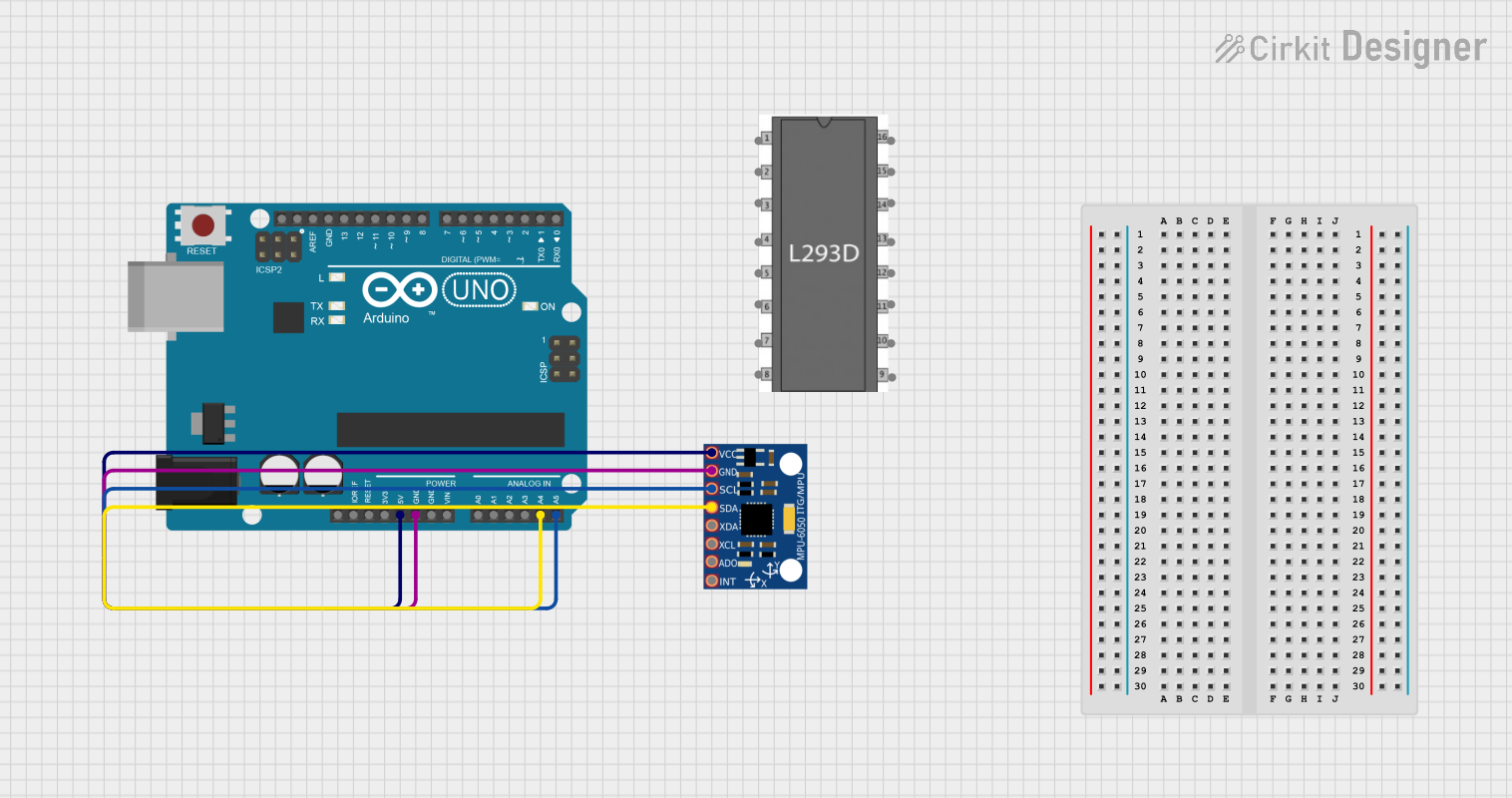
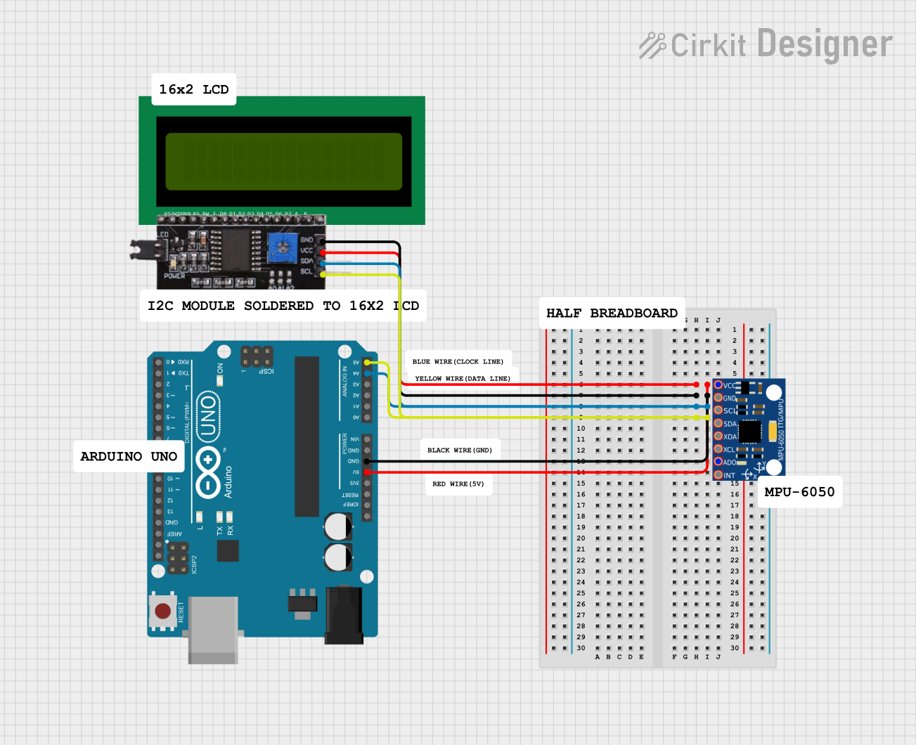
Usage Instructions
How to Use the MPU6050 in a Circuit
- Power Supply: Connect the VDD pin to a 3.3V power source and the GND pin to ground. If your microcontroller operates at 5V logic, use a level shifter for the I2C lines.
- I2C Communication: Connect the SCL and SDA pins to the corresponding I2C pins on your microcontroller. Use pull-up resistors (typically 4.7kΩ) on both lines.
- Address Selection: Set the AD0 pin to GND for the default I2C address (0x68) or to VDD for an alternate address (0x69).
- Interrupts (Optional): Connect the INT pin to a digital input pin on your microcontroller if you want to use the interrupt feature.
Important Considerations and Best Practices
- Bypass Capacitor: Place a 0.1µF ceramic capacitor close to the VDD pin for power supply decoupling.
- Mounting Orientation: Ensure the sensor is mounted securely and aligned with the desired axes of measurement.
- Calibration: Perform gyroscope and accelerometer calibration to improve accuracy.
- Temperature Effects: Be aware that temperature changes can affect sensor readings. Use the built-in temperature sensor for compensation if needed.
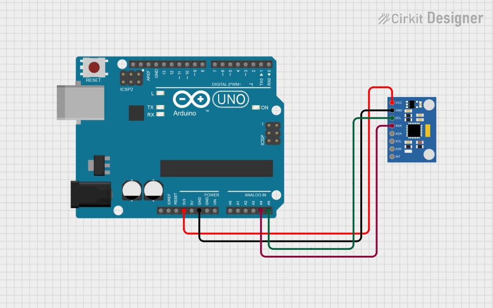
Example Code for Arduino UNO
Below is an example of how to interface the MPU6050 with an Arduino UNO using the I2C protocol:
#include <Wire.h>

// MPU6050 I2C address (default is 0x68 when AD0 is LOW)
const int MPU6050_ADDR = 0x68;

// MPU6050 register addresses
const int PWR_MGMT_1 = 0x6B; // Power management register
const int ACCEL_XOUT_H = 0x3B; // Accelerometer X-axis high byte

void setup() {
  Wire.begin(); // Initialize I2C communication
  Serial.begin(9600); // Initialize serial communication for debugging

  // Wake up the MPU6050 (clear sleep mode bit)
  Wire.beginTransmission(MPU6050_ADDR);
  Wire.write(PWR_MGMT_1); // Access power management register
  Wire.write(0); // Set to 0 to wake up the sensor
  Wire.endTransmission();
}

void loop() {
  // Request accelerometer data
  Wire.beginTransmission(MPU6050_ADDR);
  Wire.write(ACCEL_XOUT_H); // Start reading at ACCEL_XOUT_H
  Wire.endTransmission(false); // Restart I2C communication
  Wire.requestFrom(MPU6050_ADDR, 6); // Request 6 bytes (X, Y, Z high and low)

  if (Wire.available() == 6) {
    int16_t accelX = (Wire.read() << 8) | Wire.read(); // Combine high and low bytes
    int16_t accelY = (Wire.read() << 8) | Wire.read();
    int16_t accelZ = (Wire.read() << 8) | Wire.read();

    // Print accelerometer values
    Serial.print("Accel X: "); Serial.print(accelX);
    Serial.print(" | Accel Y: "); Serial.print(accelY);
    Serial.print(" | Accel Z: "); Serial.println(accelZ);
  }

  delay(500); // Wait 500ms before the next reading
}
Troubleshooting and FAQs
Common Issues and Solutions
No I2C Communication:
- Ensure the pull-up resistors (4.7kΩ) are connected to the SDA and SCL lines.
- Verify the I2C address (0x68 or 0x69) matches the AD0 pin configuration.
- Check for proper wiring and secure connections.
Incorrect or Unstable Readings:
- Perform sensor calibration to account for offsets and biases.
- Minimize vibrations and external noise during operation.
- Ensure the power supply is stable and within the specified range.
Sensor Not Responding:
- Confirm the MPU6050 is powered correctly (check VDD and GND connections).
- Verify that the microcontroller's I2C pins are configured correctly.
FAQs
Q: Can the MPU6050 be used with a 5V microcontroller?
A: Yes, but you must use a logic level shifter for the I2C lines, as the MPU6050 operates at 3.3V logic.
Q: How do I calibrate the MPU6050?
A: Calibration involves reading raw sensor data, calculating offsets, and subtracting these offsets from subsequent readings. Libraries like MPU6050 or MPU6050_DMP for Arduino often include calibration functions.
Q: What is the maximum sampling rate of the MPU6050?
A: The MPU6050 supports a maximum sampling rate of 1kHz for both the gyroscope and accelerometer.
For further details, refer to the official datasheet and application notes provided by InvenSense.