How to Use ESP8266: Examples, Pinouts, and Specs
Introduction
The ESP8266 is a low-cost Wi-Fi microchip with a full TCP/IP stack and microcontroller capability. It is widely used in Internet of Things (IoT) applications due to its affordability, ease of use, and robust wireless communication features. The chip can operate as a standalone microcontroller or as a Wi-Fi adapter for other microcontrollers, such as the Arduino.
Explore Projects Built with ESP8266
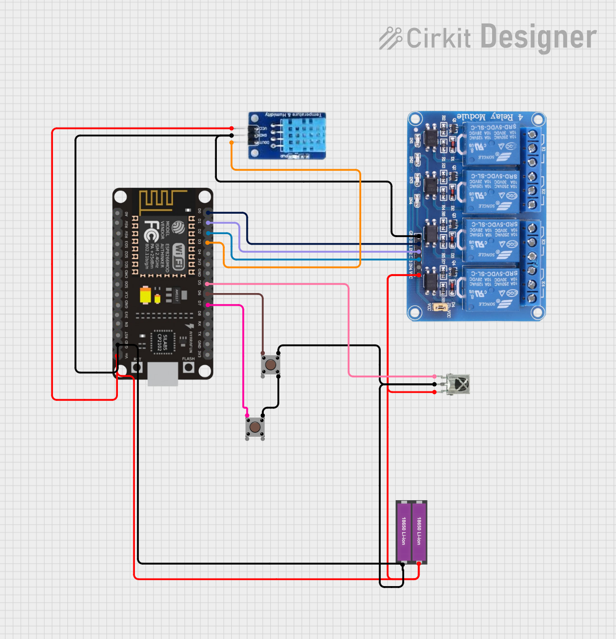

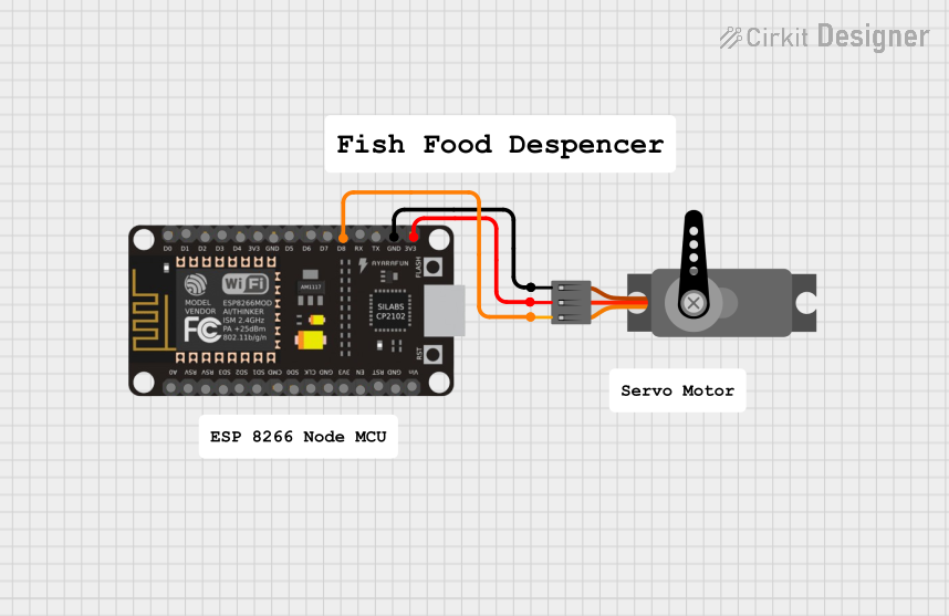

Explore Projects Built with ESP8266
Common Applications
- Home automation systems
- Wireless sensor networks
- Smart appliances
- IoT prototyping and development
- Remote monitoring and control systems
Technical Specifications
Key Technical Details
- Microcontroller: Tensilica L106 32-bit RISC processor
- Clock Speed: 80 MHz (can be overclocked to 160 MHz)
- Operating Voltage: 3.0V to 3.6V
- Wi-Fi Standards: 802.11 b/g/n
- Flash Memory: 512 KB to 4 MB (varies by module)
- GPIO Pins: Up to 17 (depending on the module)
- Communication Protocols: UART, SPI, I2C, PWM, ADC
- Power Consumption:
- Deep Sleep: ~10 µA
- Idle: ~70 mA
- Active: ~200 mA (transmitting)
- Operating Temperature: -40°C to 125°C
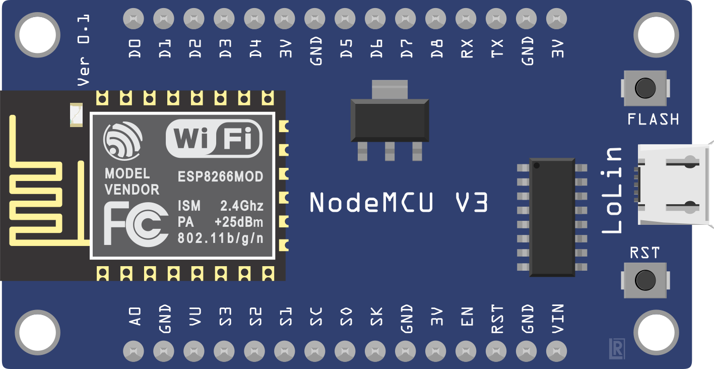
Pin Configuration and Descriptions
The ESP8266 is available in various module formats, such as ESP-01, ESP-12E, and NodeMCU. Below is the pin configuration for the ESP-12E module, one of the most commonly used variants.
| Pin | Name | Description |
|---|---|---|
| 1 | GND | Ground pin. Connect to the ground of the power supply. |
| 2 | GPIO0 | General-purpose I/O pin. Used for boot mode selection during startup. |
| 3 | GPIO2 | General-purpose I/O pin. |
| 4 | GPIO15 | General-purpose I/O pin. Must be pulled LOW during boot. |
| 5 | RXD | UART Receive pin. Used for serial communication. |
| 6 | TXD | UART Transmit pin. Used for serial communication. |
| 7 | CH_PD/EN | Chip enable pin. Must be pulled HIGH to enable the chip. |
| 8 | VCC | Power supply pin. Connect to 3.3V. |
| 9 | ADC (A0) | Analog-to-digital converter input. Accepts voltages between 0V and 1V. |
| 10 | RST | Reset pin. Pull LOW to reset the module. |
Note: Always use a voltage regulator or level shifter when interfacing the ESP8266 with 5V systems, as the module operates at 3.3V.
Usage Instructions
Using the ESP8266 in a Circuit
- Power Supply: Provide a stable 3.3V power supply to the VCC pin. Avoid directly connecting to 5V to prevent damage.
- Boot Mode Selection:
- Pull GPIO0 LOW and GPIO15 LOW for flashing firmware.
- Pull GPIO0 HIGH and GPIO15 LOW for normal operation.
- Serial Communication: Connect the RXD and TXD pins to a USB-to-serial adapter or a microcontroller for programming and communication.
- Wi-Fi Configuration: Use AT commands or custom firmware (e.g., NodeMCU or Arduino) to configure the Wi-Fi settings.
Example: Connecting ESP8266 to Arduino UNO
Below is an example of using the ESP8266 with an Arduino UNO to connect to a Wi-Fi network and send data to a server.
Circuit Connections
- Connect ESP8266 VCC to a 3.3V power source.
- Connect ESP8266 GND to ground.
- Connect ESP8266 TXD to Arduino RX (via a voltage divider to step down 5V to 3.3V).
- Connect ESP8266 RXD to Arduino TX.
- Connect ESP8266 CH_PD to 3.3V.
Arduino Code
#include <SoftwareSerial.h>

// Define RX and TX pins for SoftwareSerial
SoftwareSerial esp8266(2, 3); // RX = Pin 2, TX = Pin 3

void setup() {
  Serial.begin(9600); // Start Serial Monitor communication
  esp8266.begin(9600); // Start ESP8266 communication

  // Send AT command to test communication
  Serial.println("Sending AT command...");
  esp8266.println("AT");
  delay(1000);

  // Connect to Wi-Fi network
  Serial.println("Connecting to Wi-Fi...");
  esp8266.println("AT+CWJAP=\"YourSSID\",\"YourPassword\"");
  delay(5000);

  // Check connection status
  Serial.println("Checking connection status...");
  esp8266.println("AT+CIFSR");
  delay(2000);
}

void loop() {
  // Forward data from ESP8266 to Serial Monitor
  if (esp8266.available()) {
    Serial.write(esp8266.read());
  }

  // Forward data from Serial Monitor to ESP8266
  if (Serial.available()) {
    esp8266.write(Serial.read());
  }
}
Important: Replace
"YourSSID"and"YourPassword"with your Wi-Fi network credentials.
Best Practices
- Use a dedicated 3.3V power supply with sufficient current capacity (at least 500 mA).
- Add decoupling capacitors (e.g., 10 µF and 0.1 µF) near the VCC pin to stabilize the power supply.
- Avoid exposing the module to voltages higher than 3.6V to prevent permanent damage.
Troubleshooting and FAQs
Common Issues
ESP8266 Not Responding to AT Commands:
- Ensure the baud rate matches the module's default (usually 9600 or 115200).
- Check the wiring, especially the RX and TX connections.
- Verify that the CH_PD pin is pulled HIGH.
Wi-Fi Connection Fails:
- Double-check the SSID and password.
- Ensure the router is within range and supports 2.4 GHz (ESP8266 does not support 5 GHz).
Module Overheating:
- Verify the power supply voltage and current.
- Add a heat sink or improve ventilation if necessary.
Garbage Data in Serial Monitor:
- Ensure the baud rate in the Serial Monitor matches the ESP8266's communication baud rate.
FAQs
Can the ESP8266 be programmed directly? Yes, the ESP8266 can be programmed using the Arduino IDE or other tools by flashing custom firmware.
What is the maximum range of the ESP8266? The range is approximately 100 meters in open space, but it may vary depending on environmental factors.
Can the ESP8266 operate on 5V? No, the ESP8266 operates at 3.3V. Use a voltage regulator or level shifter when interfacing with 5V systems.
How do I reset the ESP8266? Pull the RST pin LOW momentarily to reset the module.
By following this documentation, you can effectively integrate the ESP8266 into your IoT projects and troubleshoot common issues.