How to Use Pressure Pad: Examples, Pinouts, and Specs

Introduction
A pressure pad is a type of sensor designed to detect physical pressure applied to its surface. It operates by converting mechanical force into an electrical signal, which can then be processed by a circuit or microcontroller. Pressure pads are widely used in applications such as security systems (e.g., detecting intrusions), gaming controllers (e.g., pressure-sensitive buttons), and interactive electronic devices. Their simplicity, reliability, and versatility make them a popular choice for various projects and commercial products.
Explore Projects Built with Pressure Pad
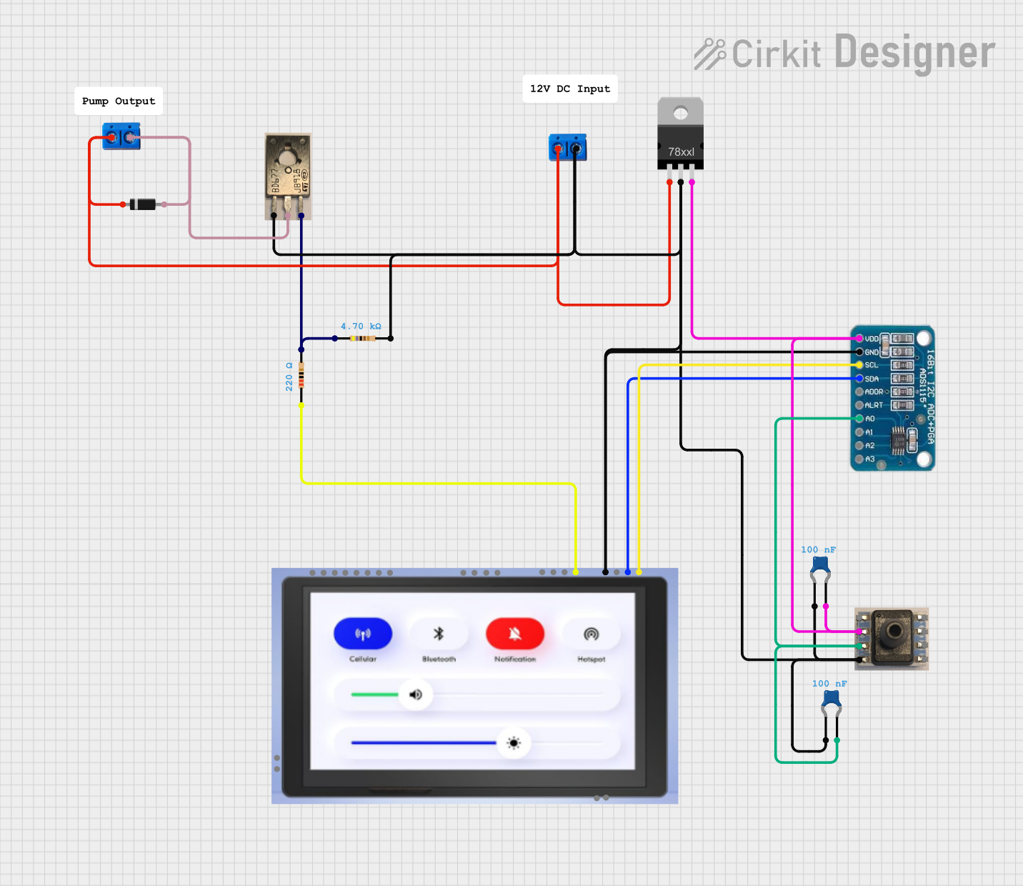
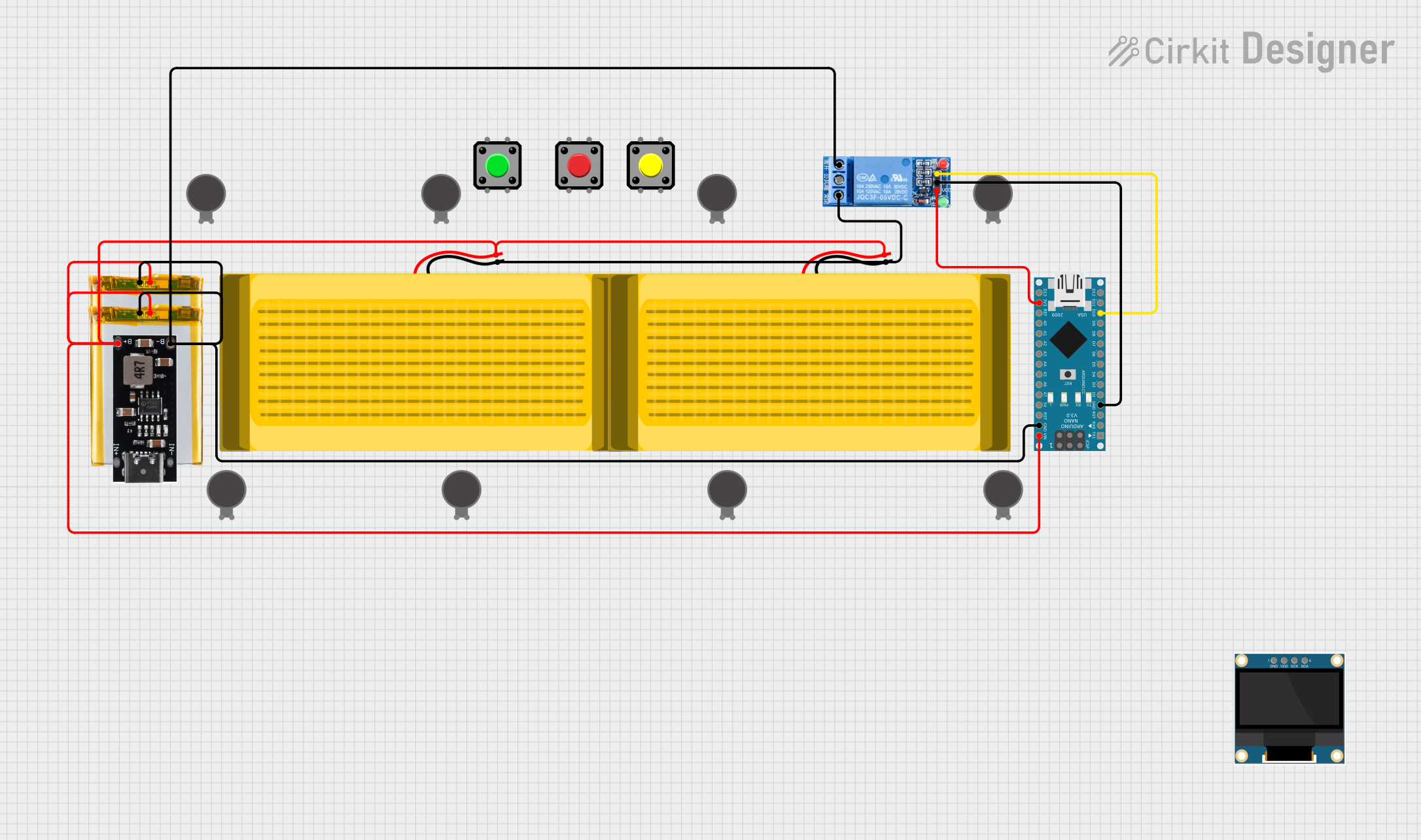
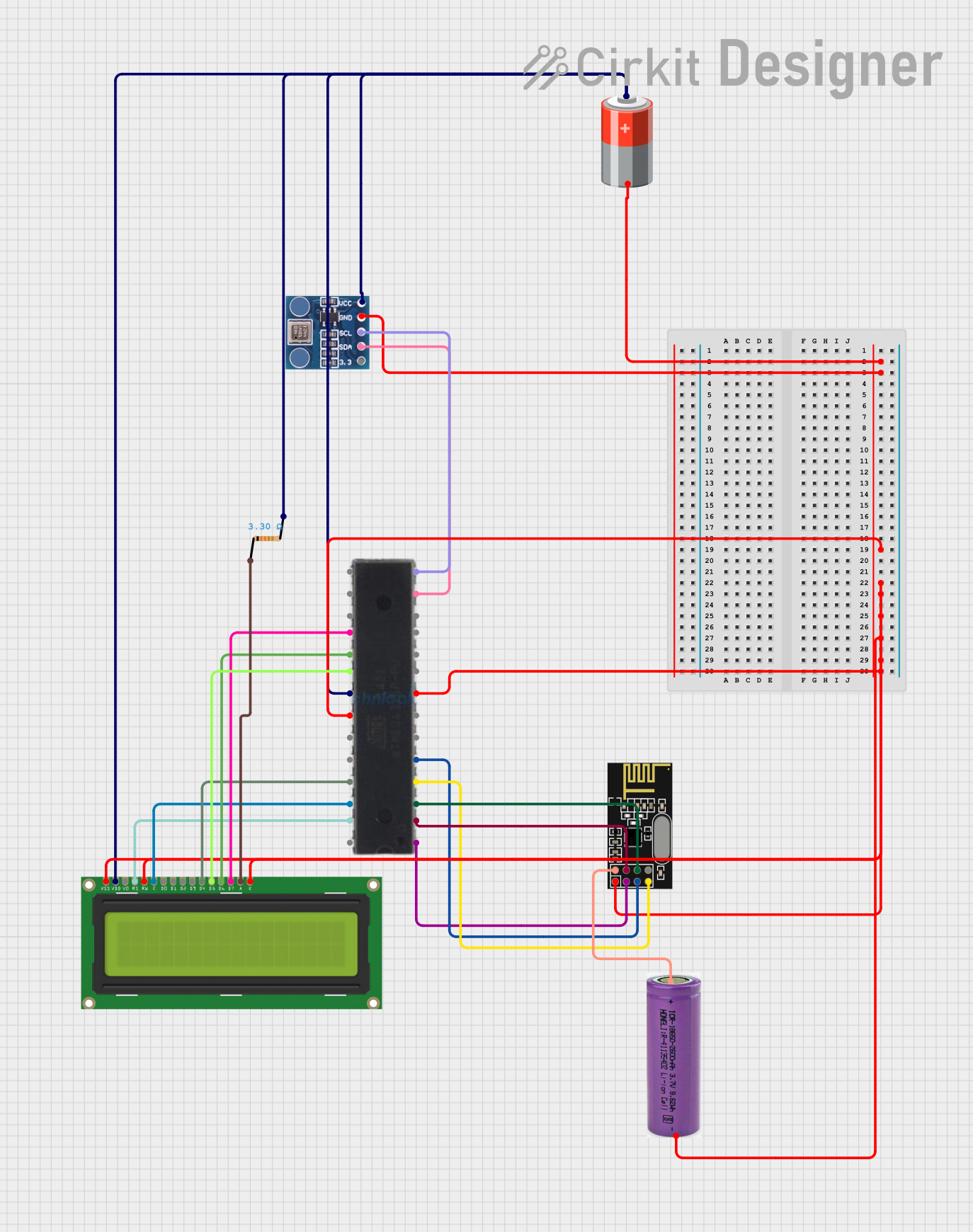
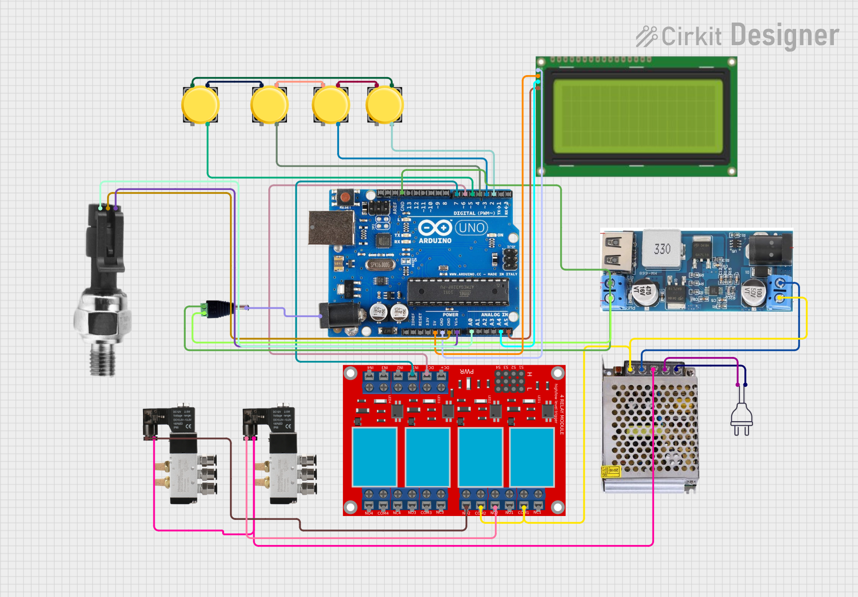
Explore Projects Built with Pressure Pad
Technical Specifications
Below are the general technical specifications for a standard pressure pad. Note that specific models may vary slightly in their ratings and features.
- Operating Voltage: 3.3V to 5V DC
- Operating Current: < 10mA
- Output Type: Analog or Digital (depending on the model)
- Pressure Sensitivity: Typically ranges from 100g to 10kg
- Response Time: < 10ms
- Operating Temperature: -10°C to 50°C
- Lifespan: Up to 1 million activations (varies by manufacturer)
Pin Configuration and Descriptions
The pressure pad typically has two or three pins, depending on the model. Below is a table describing the pin configuration:
| Pin | Name | Description |
|---|---|---|
| 1 | Signal (OUT) | Outputs the signal based on the pressure applied. Can be analog or digital. |
| 2 | VCC | Connects to the positive voltage supply (3.3V or 5V). |
| 3 | GND | Connects to the ground of the circuit. |
For two-pin models, the pins are typically Signal and GND, with the signal pin also serving as the power input.
Usage Instructions
How to Use the Pressure Pad in a Circuit
Wiring the Pressure Pad:
- Connect the VCC pin to a 3.3V or 5V power source.
- Connect the GND pin to the ground of your circuit.
- Connect the Signal (OUT) pin to an analog or digital input pin on your microcontroller (e.g., Arduino).
Reading the Output:
- For analog pressure pads, the output voltage varies with the applied pressure. Use an analog-to-digital converter (ADC) to read the signal.
- For digital pressure pads, the output is either HIGH (when pressure is detected) or LOW (when no pressure is detected).
Example Circuit:
- Use a pull-down resistor (10kΩ) on the signal pin to ensure stable readings.
- Optionally, add a capacitor (e.g., 0.1µF) across the power pins to filter noise.
Arduino UNO Example Code
Below is an example of how to use a pressure pad with an Arduino UNO:
// Define the pin connected to the pressure pad
const int pressurePadPin = A0; // Analog pin A0 for reading pressure pad signal

void setup() {
  Serial.begin(9600); // Initialize serial communication at 9600 baud
  pinMode(pressurePadPin, INPUT); // Set the pressure pad pin as input
}

void loop() {
  // Read the analog value from the pressure pad
  int pressureValue = analogRead(pressurePadPin);

  // Print the pressure value to the Serial Monitor
  Serial.print("Pressure Value: ");
  Serial.println(pressureValue);

  // Add a small delay to stabilize readings
  delay(100);
}
Important Considerations and Best Practices
- Voltage Compatibility: Ensure the pressure pad's operating voltage matches your circuit's power supply.
- Debouncing: For digital pressure pads, implement software debouncing to avoid false triggers.
- Placement: Install the pressure pad on a flat, stable surface to ensure accurate readings.
- Load Limits: Avoid exceeding the pressure pad's maximum load capacity to prevent damage.
Troubleshooting and FAQs
Common Issues and Solutions
No Output Signal:
- Check the wiring and ensure all connections are secure.
- Verify that the power supply voltage matches the pressure pad's requirements.
- Test the pressure pad with a multimeter to confirm functionality.
Inconsistent Readings:
- Add a pull-down resistor to stabilize the signal.
- Ensure the pressure pad is not exposed to excessive vibrations or environmental noise.
- Use a capacitor to filter out electrical noise.
Signal Always HIGH or LOW:
- Verify that the pressure pad is not damaged or worn out.
- Check for short circuits or loose connections in the wiring.
FAQs
Q: Can I use a pressure pad with a Raspberry Pi?
A: Yes, you can connect a pressure pad to a Raspberry Pi. For analog pressure pads, use an external ADC module since the Raspberry Pi lacks built-in analog input.
Q: How do I clean a pressure pad?
A: Use a soft, dry cloth to clean the surface. Avoid using water or harsh chemicals, as they may damage the sensor.
Q: Can I use multiple pressure pads in one circuit?
A: Yes, you can connect multiple pressure pads to different input pins on your microcontroller. Ensure each pad has its own pull-down resistor if needed.
Q: What happens if I exceed the pressure pad's load limit?
A: Exceeding the load limit may permanently damage the pressure pad or reduce its lifespan. Always adhere to the manufacturer's specifications.