How to Use shunt 200A: Examples, Pinouts, and Specs
Introduction
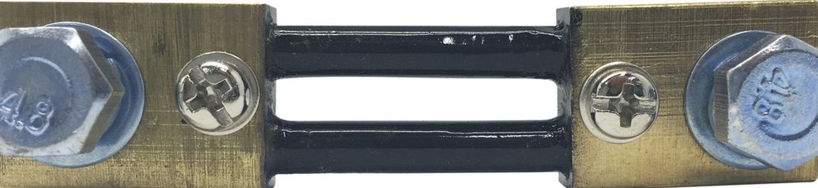
A shunt is a precision resistor designed to measure current by generating a small voltage drop proportional to the current flowing through it. The Shunt 200A is specifically rated to handle currents up to 200 amperes, making it suitable for high-current applications. It is commonly used in conjunction with ammeters, microcontrollers, or data acquisition systems to monitor and measure current in electrical circuits.
Explore Projects Built with shunt 200A


Explore Projects Built with shunt 200A
Common Applications and Use Cases
- Battery management systems (BMS) for electric vehicles and renewable energy systems
- High-current power supplies and industrial equipment
- Monitoring and controlling current in DC circuits
- Integration with microcontrollers (e.g., Arduino, Raspberry Pi) for current sensing
- Overcurrent protection and diagnostics in electrical systems
Technical Specifications
The Shunt 200A is designed to provide accurate current measurements while maintaining durability under high-current conditions. Below are its key specifications:
| Parameter | Value |
|---|---|
| Rated Current | 200A |
| Resistance | Typically 50 µΩ (micro-ohms) |
| Voltage Drop | 75mV at 200A |
| Accuracy | ±0.5% |
| Operating Temperature | -40°C to +85°C |
| Material | Manganin or similar alloy |
| Mounting Style | Screw terminals |
Pin Configuration and Descriptions
The Shunt 200A typically has two main connection points for current flow and two smaller terminals for voltage measurement. Below is the pin configuration:
| Pin/Terminal | Description |
|---|---|
| Current Input Terminal | Connects to the positive side of the circuit where current enters the shunt. |
| Current Output Terminal | Connects to the load or negative side of the circuit where current exits. |
| Voltage Sense (+) | Positive voltage sense terminal for measuring the voltage drop across the shunt. |
| Voltage Sense (-) | Negative voltage sense terminal for measuring the voltage drop across the shunt. |
Usage Instructions
How to Use the Shunt 200A in a Circuit
Placement in the Circuit:
- Place the shunt in series with the load whose current you want to measure.
- Ensure the current flows from the Current Input Terminal to the Current Output Terminal.
Voltage Measurement:
- Connect the Voltage Sense (+) and Voltage Sense (-) terminals to a voltmeter, ADC (Analog-to-Digital Converter), or microcontroller.
- The voltage drop across the shunt is proportional to the current flowing through it. For example, at 200A, the voltage drop will be 75mV.
Calculating Current:
- Use Ohm's Law to calculate the current:
[ I = \frac{V}{R} ]
Where (I) is the current, (V) is the measured voltage drop, and (R) is the resistance of the shunt (e.g., 50 µΩ).
- Use Ohm's Law to calculate the current:
Connection to Microcontrollers:
- If using a microcontroller like an Arduino UNO, connect the Voltage Sense (+) terminal to an analog input pin and the Voltage Sense (-) terminal to the ground (GND).
- Use the ADC to read the voltage drop and calculate the current in software.
Important Considerations and Best Practices
- Current Rating: Do not exceed the 200A rating to avoid overheating or damaging the shunt.
- Voltage Drop: Ensure the voltage drop (e.g., 75mV) is within the input range of your measurement device.
- Wiring: Use thick, low-resistance wires for the current terminals to minimize additional resistance.
- Calibration: Periodically calibrate the shunt and measurement system for accurate readings.
- Thermal Management: Ensure proper ventilation or cooling if the shunt operates near its maximum current rating.
Example Code for Arduino UNO
Below is an example of how to use the Shunt 200A with an Arduino UNO to measure current:
// Define constants for the shunt
const float shuntResistance = 0.00005; // Shunt resistance in ohms (50 µΩ)
const float adcReferenceVoltage = 5.0; // Reference voltage for Arduino ADC
const int adcResolution = 1024;        // ADC resolution (10-bit)

// Define the analog pin connected to the shunt's voltage sense terminals
const int shuntVoltagePin = A0;

void setup() {
  Serial.begin(9600); // Initialize serial communication
}

void loop() {
  // Read the raw ADC value from the shunt
  int adcValue = analogRead(shuntVoltagePin);

  // Convert the ADC value to a voltage
  float shuntVoltage = (adcValue * adcReferenceVoltage) / adcResolution;

  // Calculate the current using Ohm's Law
  float current = shuntVoltage / shuntResistance;

  // Print the current to the Serial Monitor
  Serial.print("Current: ");
  Serial.print(current);
  Serial.println(" A");

  delay(1000); // Wait for 1 second before the next reading
}
Troubleshooting and FAQs
Common Issues and Solutions
No Voltage Reading Across the Shunt:
- Cause: Improper wiring or loose connections.
- Solution: Verify that the shunt is properly connected in series with the load and that all terminals are securely fastened.
Inaccurate Current Measurements:
- Cause: Incorrect shunt resistance value used in calculations.
- Solution: Double-check the shunt's resistance (e.g., 50 µΩ) and ensure it matches the value used in your calculations.
Overheating of the Shunt:
- Cause: Current exceeds the 200A rating.
- Solution: Reduce the current or use a higher-rated shunt.
Microcontroller Reads Zero Current:
- Cause: Voltage drop is too small for the ADC to detect.
- Solution: Use an amplifier circuit to increase the voltage drop before feeding it to the ADC.
FAQs
Q: Can I use the Shunt 200A for AC current measurement?
A: The Shunt 200A is primarily designed for DC current measurement. For AC applications, additional circuitry (e.g., rectifiers) is required.
Q: How do I protect the shunt from overcurrent?
A: Use a fuse or circuit breaker rated slightly above 200A to protect the shunt from excessive current.
Q: Can I use the shunt with a 3.3V microcontroller?
A: Yes, but ensure the voltage drop across the shunt is within the ADC input range of the microcontroller. You may need an amplifier for better resolution.