How to Use USB-C PD trigger board: Examples, Pinouts, and Specs
Introduction
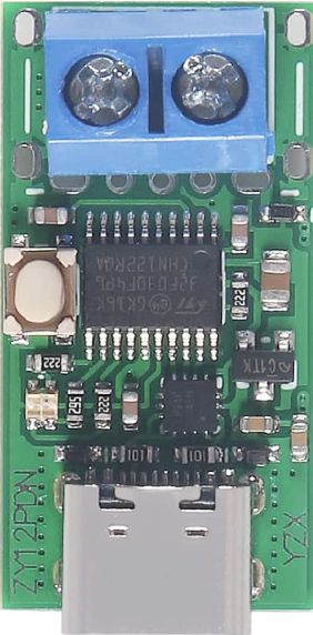
The USB-C PD Trigger Board (ZY12PDN), manufactured by YZXSTUDIO, is a compact and versatile module designed to negotiate power levels over a USB-C connection. It leverages the USB Power Delivery (PD) protocol to request specific voltage and current levels from a USB-C power source, enabling higher power delivery to compatible devices. This makes it an essential tool for prototyping, testing, and powering devices that require precise voltage and current settings.
Explore Projects Built with USB-C PD trigger board


Explore Projects Built with USB-C PD trigger board
Common Applications and Use Cases
- Powering development boards (e.g., Arduino, Raspberry Pi) with specific voltage requirements.
- Testing USB-C power adapters for compliance with PD standards.
- Prototyping circuits that require adjustable power levels.
- Powering high-current devices such as motors, LEDs, or charging batteries.
- Educational purposes for understanding USB-C PD negotiation.
Technical Specifications
Key Technical Details
- Manufacturer: YZXSTUDIO
- Part ID: ZY12PDN
- Input Voltage: 5V to 20V (via USB-C power source)
- Output Voltage Options: 5V, 9V, 12V, 15V, 20V (selectable via onboard configuration)
- Maximum Output Current: Up to 5A (depending on the power source and selected voltage)
- Power Delivery Protocol: USB-C PD 2.0/3.0 compliant
- Dimensions: Compact form factor (approximately 25mm x 15mm)
- Operating Temperature: -20°C to 85°C
Pin Configuration and Descriptions
The ZY12PDN board has a simple pinout for easy integration into circuits. Below is the pin configuration:
| Pin Name | Description |
|---|---|
VOUT+ |
Positive output voltage terminal. Connect to the load's positive input. |
VOUT- |
Negative output voltage terminal. Connect to the load's ground. |
CC1 |
USB-C Configuration Channel 1. Used for PD negotiation. |
CC2 |
USB-C Configuration Channel 2. Used for PD negotiation. |
GND |
Ground connection for the board. |
SEL |
Voltage selection pin. Used to configure the desired output voltage. |
Usage Instructions
How to Use the Component in a Circuit
Connect the USB-C Power Source:
Plug a USB-C power adapter into the USB-C port on the ZY12PDN board. Ensure the adapter supports the desired voltage and current levels.Select the Desired Output Voltage:
Use theSELpin to configure the output voltage. This is typically done by connecting theSELpin to ground or leaving it floating, depending on the desired voltage. Refer to the manufacturer's datasheet for the exact voltage selection configuration.Connect the Load:
Attach the load to theVOUT+andVOUT-terminals. Ensure the load's voltage and current requirements are within the board's capabilities.Power On:
Once everything is connected, the board will negotiate with the USB-C power source to deliver the selected voltage to the load.
Important Considerations and Best Practices
- Check Power Source Compatibility: Ensure the USB-C power adapter supports the desired voltage and current levels.
- Avoid Overloading: Do not exceed the maximum current rating of the board or the power source.
- Heat Dissipation: If operating at high currents, ensure adequate ventilation or cooling to prevent overheating.
- Voltage Selection: Double-check the voltage selection configuration to avoid damaging the connected load.
- Polarity: Always connect the load with the correct polarity to prevent damage.
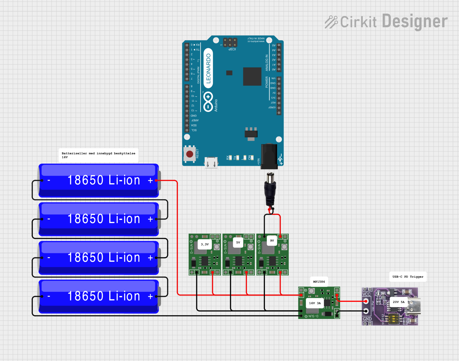
Example: Using with an Arduino UNO
The ZY12PDN can be used to power an Arduino UNO at 9V. Below is an example setup:
- Connect a USB-C power adapter to the ZY12PDN board.
- Configure the
SELpin for 9V output (refer to the datasheet for the exact configuration). - Connect the
VOUT+terminal to the Arduino's VIN pin and theVOUT-terminal to the GND pin. - Power on the USB-C adapter, and the Arduino UNO will receive 9V through the VIN pin.
Troubleshooting and FAQs
Common Issues and Solutions
| Issue | Possible Cause | Solution |
|---|---|---|
| No output voltage | USB-C power source does not support the requested voltage/current. | Use a compatible USB-C power adapter that supports the desired PD profile. |
| Incorrect output voltage | Voltage selection configuration is incorrect. | Verify the SEL pin configuration and adjust as needed. |
| Overheating of the board | Excessive current draw or inadequate cooling. | Reduce the load current or improve ventilation around the board. |
| Load not powering on | Polarity mismatch or insufficient power. | Check the polarity and ensure the power source meets the load's requirements. |
| Board not negotiating with the power source | Faulty USB-C cable or incompatible power adapter. | Use a high-quality USB-C cable and a PD-compliant power adapter. |
FAQs
Can the ZY12PDN board be used with non-PD USB-C adapters?
No, the board requires a USB-C power adapter that supports the Power Delivery (PD) protocol.What is the maximum power output of the ZY12PDN?
The maximum power output depends on the selected voltage and the power source's current capability. For example, at 20V, the board can deliver up to 100W (20V x 5A) if the power source supports it.How do I select a specific output voltage?
The output voltage is configured using theSELpin. Refer to the manufacturer's datasheet for the exact voltage selection method.Can I use the ZY12PDN to charge batteries?
Yes, but ensure the battery charging circuit is compatible with the selected output voltage and current.Is the ZY12PDN board safe for continuous operation?
Yes, as long as the board is operated within its specified voltage, current, and temperature limits.
This documentation provides a comprehensive guide to using the USB-C PD Trigger Board (ZY12PDN) effectively. For additional details, refer to the manufacturer's datasheet or contact YZXSTUDIO support.