How to Use Adafruit MiniBoost 5V 100mA Charge Pump AP3602A: Examples, Pinouts, and Specs
Introduction
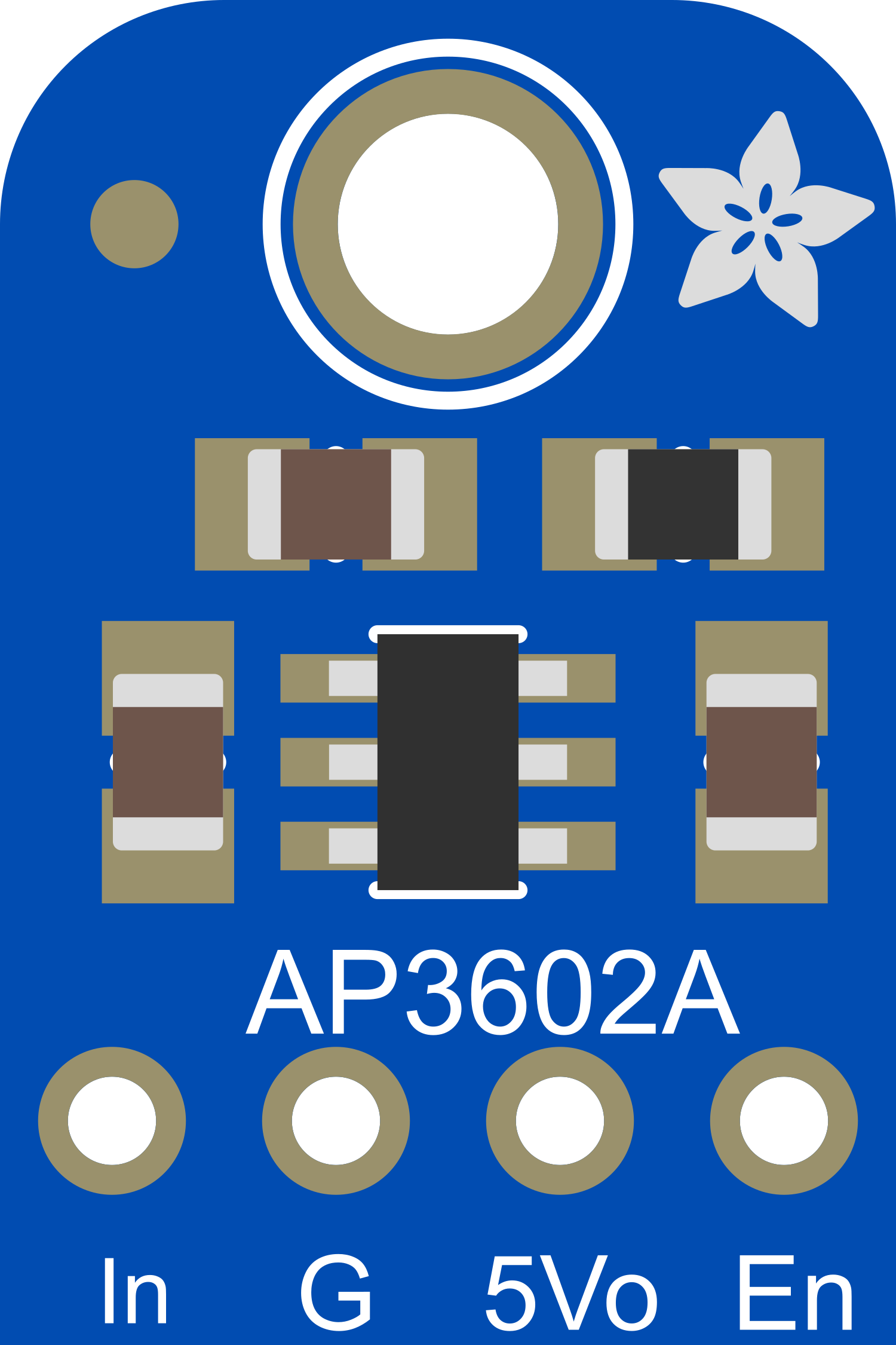
The Adafruit MiniBoost 5V 100mA Charge Pump AP3602A is a compact, efficient voltage booster module designed to increase an input voltage to a stable 5V output, capable of delivering up to 100mA of current. This component is ideal for low-power applications that require a consistent 5V supply, such as battery-powered devices, wearables, or small electronics projects. Its small footprint and ease of use make it a popular choice for hobbyists and professionals alike.
Explore Projects Built with Adafruit MiniBoost 5V 100mA Charge Pump AP3602A
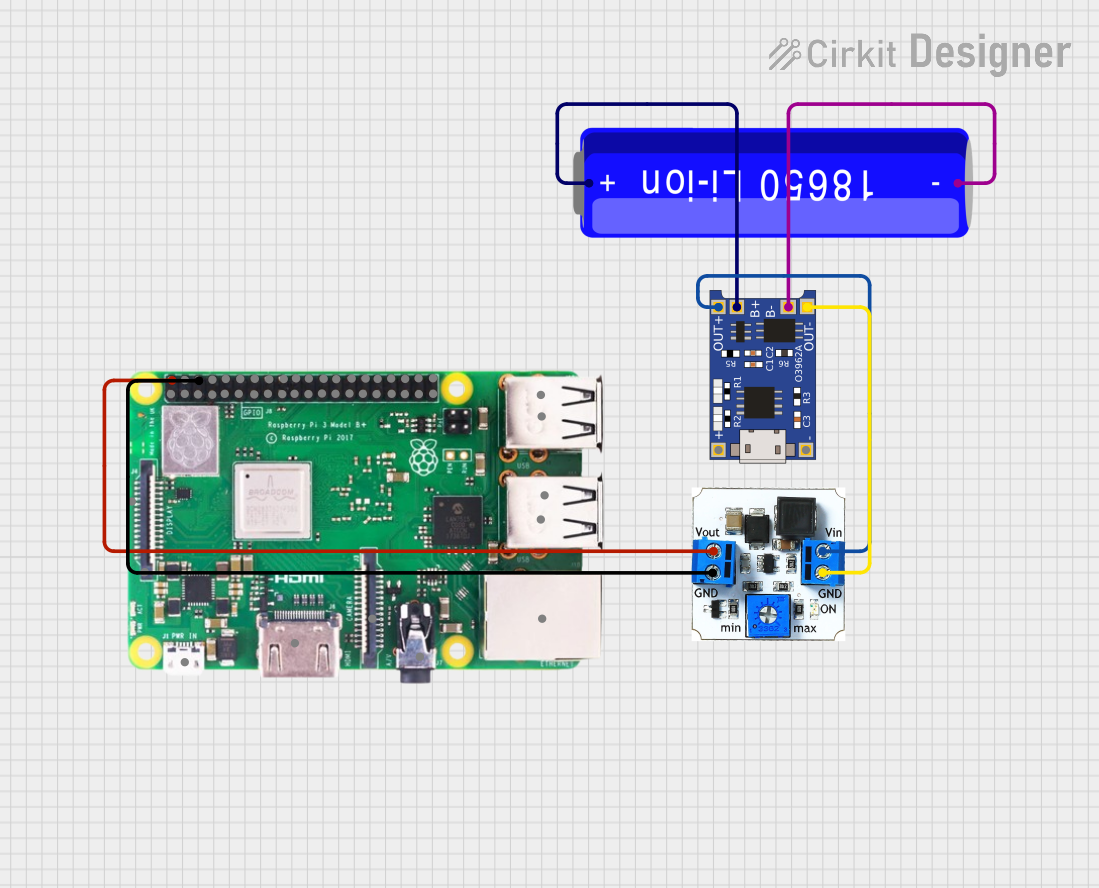


Explore Projects Built with Adafruit MiniBoost 5V 100mA Charge Pump AP3602A
Common Applications and Use Cases
- Battery-powered projects requiring a 5V supply
- Wearable electronics
- Portable devices
- Small-scale robotics
- Microcontroller boards without a stable 5V output
Technical Specifications
Key Technical Details
- Input Voltage Range: 2.0V to 5.5V
- Output Voltage: 5V ± 4%
- Maximum Output Current: 100mA
- Quiescent Current: 120µA typical
- Efficiency: Up to 90%
- Operating Temperature Range: -40°C to +85°C
Pin Configuration and Descriptions
| Pin Number | Name | Description |
|---|---|---|
| 1 | VIN | Input voltage (2.0V to 5.5V) |
| 2 | GND | Ground connection |
| 3 | VOUT | Regulated 5V output |
| 4 | EN | Enable pin (active high) |
Usage Instructions
How to Use the Component in a Circuit
Power Connections:
- Connect the VIN pin to your input voltage source (2.0V to 5.5V).
- Connect the GND pin to the common ground of your system.
Enable the Charge Pump:
- The EN pin can be left unconnected for always-on operation, as it has an internal pull-up.
- For controlled operation, connect the EN pin to a digital output of a microcontroller to enable or disable the charge pump as needed.
Output Voltage:
- The VOUT pin will provide a stable 5V output when the module is enabled.
- Ensure that the current draw does not exceed 100mA.
Important Considerations and Best Practices
- Input Voltage: Do not exceed the recommended input voltage range to prevent damage.
- Heat Dissipation: Although the module is efficient, always check for excessive heat when drawing maximum current.
- Mounting: Secure the module to prevent movement that could lead to intermittent connections.
- Decoupling Capacitors: Use decoupling capacitors close to the input and output pins to minimize voltage spikes and noise.
Troubleshooting and FAQs
Common Issues
- Insufficient Output Voltage: Ensure that the input voltage is within the specified range and that the current draw is below 100mA.
- Module Not Powering On: Check the EN pin is pulled high if not always-on operation is desired.
- Excessive Noise on Output: Add decoupling capacitors or check for sources of electromagnetic interference.
Solutions and Tips for Troubleshooting
- Verify Connections: Double-check all wiring, especially the power and ground connections.
- Measure Input Voltage: Use a multimeter to confirm that the input voltage is within the specified range.
- Check Load Current: Ensure that the load does not exceed the 100mA maximum output current.
- Inspect for Damage: Look for any signs of physical damage or overheating on the module.
FAQs
Q: Can I use the MiniBoost with a 3.3V input? A: Yes, the MiniBoost can boost voltages from as low as 2.0V to 5V.
Q: Is it possible to disable the MiniBoost when not in use? A: Yes, you can disable the MiniBoost by pulling the EN pin low.
Q: What is the maximum input voltage for the MiniBoost? A: The maximum input voltage should not exceed 5.5V.
Q: How can I ensure a stable output voltage? A: Use decoupling capacitors and avoid drawing more than the maximum rated current.
Example Code for Arduino UNO
// Example code to enable and disable the Adafruit MiniBoost 5V 100mA Charge Pump

const int enablePin = 7; // Connect the EN pin of the MiniBoost to digital pin 7

void setup() {
  pinMode(enablePin, OUTPUT); // Set the enable pin as an output
  digitalWrite(enablePin, HIGH); // Enable the MiniBoost
}

void loop() {
  // Your code here to perform tasks while the MiniBoost is enabled

  // To disable the MiniBoost, set the enablePin to LOW
  // digitalWrite(enablePin, LOW);

  // To re-enable the MiniBoost, set the enablePin to HIGH
  // digitalWrite(enablePin, HIGH);
}
Remember to keep the code comments concise and within the 80 character line length limit. This example demonstrates how to control the Adafruit MiniBoost using an Arduino UNO by enabling or disabling the charge pump through a digital pin.