How to Use sim a7670c r2 4g lte cat 1 module: Examples, Pinouts, and Specs
Introduction
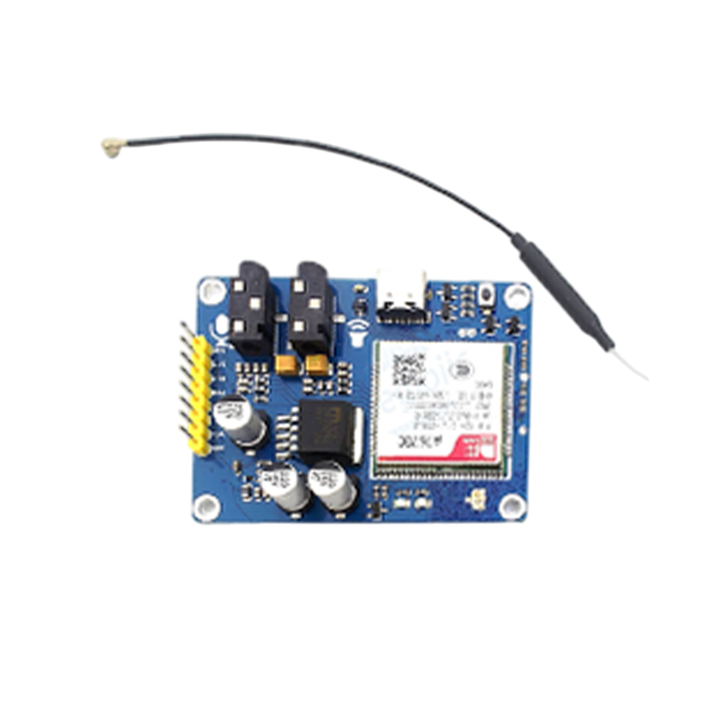
The SIM A7670C R2 is a compact 4G LTE module manufactured by SIMCom, designed specifically for IoT (Internet of Things) applications. It supports Category 1 (Cat 1) data rates, making it ideal for applications requiring efficient communication and low power consumption. This module is well-suited for smart metering, asset tracking, industrial automation, and other IoT use cases where reliable connectivity is essential.
Explore Projects Built with sim a7670c r2 4g lte cat 1 module


Explore Projects Built with sim a7670c r2 4g lte cat 1 module
Common Applications
- Smart metering (electricity, water, gas)
- Asset tracking and fleet management
- Industrial automation and control systems
- Smart home and security systems
- Wearable devices and health monitoring
- Point-of-Sale (POS) terminals
Technical Specifications
Key Technical Details
| Parameter | Specification |
|---|---|
| Manufacturer | SIMCom |
| Part Number | SIM A7670C |
| Network Support | 4G LTE Cat 1, GSM/GPRS/EDGE fallback |
| Frequency Bands | LTE: B1/B3/B5/B7/B8/B20/B28 |
| Data Rate (LTE Cat 1) | Uplink: 5 Mbps, Downlink: 10 Mbps |
| Operating Voltage | 3.3V to 4.3V (Typical: 3.8V) |
| Power Consumption | Idle: ~1.2mA, Active: ~500mA |
| Operating Temperature | -40°C to +85°C |
| Dimensions | 24mm x 24mm x 2.4mm |
| Interface Support | UART, USB 2.0, GPIO, I2C, SPI |
| SIM Card Support | 1.8V/3.0V |
| GNSS Support | GPS, GLONASS, BeiDou, Galileo |
| Firmware Update | FOTA (Firmware Over-The-Air) |
Pin Configuration and Descriptions
The SIM A7670C module has a total of 42 pins. Below is a summary of the key pins:
| Pin Number | Pin Name | Description |
|---|---|---|
| 1 | VCC | Power supply input (3.3V to 4.3V) |
| 2 | GND | Ground |
| 3 | TXD | UART Transmit Data |
| 4 | RXD | UART Receive Data |
| 5 | USB_DP | USB Data Positive |
| 6 | USB_DM | USB Data Negative |
| 7 | SIM_VDD | SIM card power supply |
| 8 | SIM_CLK | SIM card clock |
| 9 | SIM_DATA | SIM card data |
| 10 | SIM_RST | SIM card reset |
| 11 | GPIO1 | General Purpose I/O |
| 12 | GPIO2 | General Purpose I/O |
| 13 | GNSS_TXD | GNSS UART Transmit Data |
| 14 | GNSS_RXD | GNSS UART Receive Data |
| 15 | RESET | Module reset (active low) |
For a complete pinout, refer to the official SIMCom datasheet.
Usage Instructions
How to Use the SIM A7670C in a Circuit
- Power Supply: Connect the module's
VCCpin to a stable power source (3.8V typical) andGNDto ground. Ensure the power supply can handle peak currents of up to 2A. - UART Communication: Connect the
TXDandRXDpins to a microcontroller or host device for serial communication. Use a level shifter if the host operates at 5V logic levels. - SIM Card Interface: Connect a 1.8V or 3.0V SIM card to the
SIM_VDD,SIM_CLK,SIM_DATA, andSIM_RSTpins. - Antenna Connection: Attach a 4G LTE antenna to the module's antenna connector for optimal signal reception.
- GNSS Functionality: If GNSS is required, connect the
GNSS_TXDandGNSS_RXDpins to the host device and attach a GNSS antenna.
Important Considerations
- Power Supply Stability: Use decoupling capacitors (e.g., 100µF and 0.1µF) near the
VCCpin to ensure stable operation. - Antenna Placement: Place the antenna away from noise sources and ensure proper grounding for optimal performance.
- Reset Pin: Use the
RESETpin to restart the module if it becomes unresponsive. - Firmware Updates: Regularly update the module's firmware via FOTA to ensure compatibility and security.
Example: Connecting to an Arduino UNO
Below is an example of how to connect the SIM A7670C to an Arduino UNO and send an AT command to check network registration.
Wiring
| SIM A7670C Pin | Arduino UNO Pin |
|---|---|
| VCC | 3.3V (external supply recommended) |
| GND | GND |
| TXD | Pin 10 (RX) |
| RXD | Pin 11 (TX) |
| RESET | Pin 9 |
Code Example
#include <SoftwareSerial.h>

// Define software serial pins for communication with SIM A7670C
SoftwareSerial simModule(10, 11); // RX = Pin 10, TX = Pin 11

void setup() {
  // Initialize serial communication
  Serial.begin(9600); // For debugging with PC
  simModule.begin(9600); // For communication with SIM A7670C

  // Send a reset signal to the module
  pinMode(9, OUTPUT);
  digitalWrite(9, LOW); // Pull RESET pin low
  delay(100);           // Wait for 100ms
  digitalWrite(9, HIGH); // Release RESET pin

  Serial.println("Initializing SIM A7670C...");
  delay(2000); // Wait for the module to initialize

  // Send an AT command to check network registration
  simModule.println("AT+CREG?");
}

void loop() {
  // Read and display responses from the module
  if (simModule.available()) {
    String response = simModule.readString();
    Serial.println("SIM A7670C Response: " + response);
  }
}
Notes
- Ensure the Arduino's 3.3V pin is not overloaded. Use an external power supply for the module if necessary.
- Use a logic level shifter if the Arduino operates at 5V logic levels.
Troubleshooting and FAQs
Common Issues and Solutions
Module Not Powering On
- Ensure the power supply provides a stable voltage (3.8V typical) and sufficient current (up to 2A).
- Check the connections to the
VCCandGNDpins.
No Response to AT Commands
- Verify the UART connections (
TXDandRXD) and ensure the baud rate matches (default: 9600). - Check if the module is properly initialized and powered on.
- Verify the UART connections (
SIM Card Not Detected
- Ensure the SIM card is inserted correctly and supports 1.8V or 3.0V operation.
- Check the connections to the SIM interface pins (
SIM_VDD,SIM_CLK,SIM_DATA,SIM_RST).
Poor Signal Reception
- Verify the antenna is securely connected and placed in an area with good network coverage.
- Avoid placing the module near sources of electromagnetic interference.
FAQs
Q: Can the SIM A7670C operate on 2G networks?
A: Yes, the module supports GSM/GPRS/EDGE as a fallback for areas without 4G LTE coverage.
Q: How do I update the firmware?
A: Use the FOTA (Firmware Over-The-Air) feature or contact SIMCom for firmware update tools and instructions.
Q: What is the maximum data rate supported?
A: The module supports up to 10 Mbps downlink and 5 Mbps uplink on LTE Cat 1 networks.
Q: Does the module support GNSS?
A: Yes, the SIM A7670C supports GPS, GLONASS, BeiDou, and Galileo for positioning and navigation.
For further assistance, refer to the official SIMCom documentation or contact technical support.