How to Use DC Source: Examples, Pinouts, and Specs
Introduction
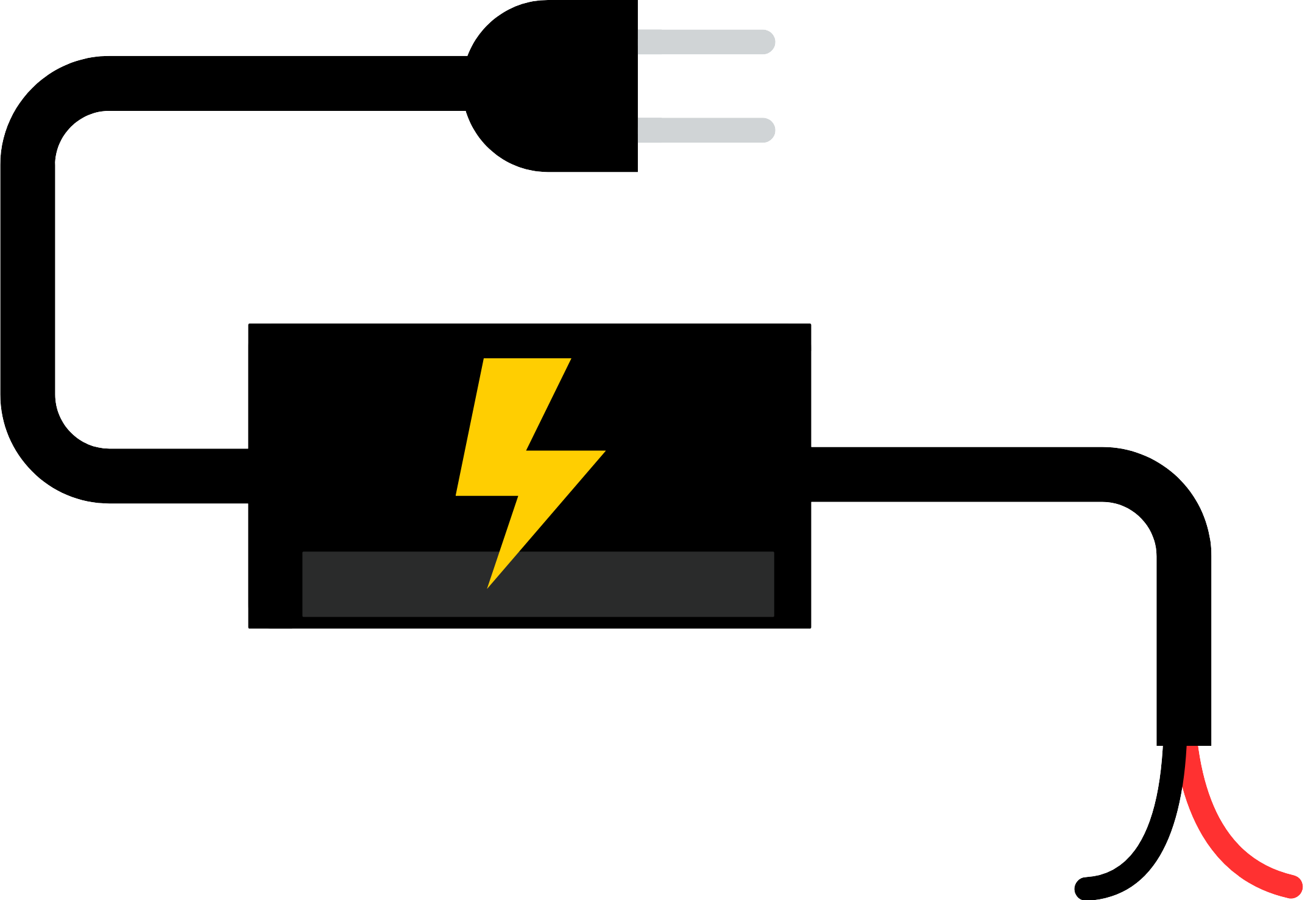
A DC (Direct Current) source is an electronic component that provides a constant voltage output, which is essential for powering electronic circuits and devices. Unlike AC (Alternating Current) sources, which periodically reverse direction, DC sources maintain a steady flow of electricity in one direction. Common applications for DC sources include battery charging, powering electronic devices such as laptops and smartphones, and as a power supply for electronic projects, including those involving microcontrollers like the Arduino UNO.
Explore Projects Built with DC Source


Explore Projects Built with DC Source
Technical Specifications
General Specifications
| Parameter | Value Range | Description |
|---|---|---|
| Output Voltage | X V to Y V | The range of voltage the DC source can provide. |
| Output Current | A mA to B mA | Maximum current available at the output. |
| Power Ratings | C W | Total power the DC source can deliver. |
| Input Voltage | D V to E V AC/DC | The voltage range for the input power. |
| Efficiency | F % | The efficiency of the power conversion. |
| Operating Temperature | G°C to H°C | The temperature range within which the DC source operates safely. |
Pin Configuration and Descriptions
| Pin Number | Name | Description |
|---|---|---|
| 1 | Vout (+) | Positive output voltage terminal providing the DC output. |
| 2 | GND | Ground terminal, the reference point for the output voltage. |
| 3 | Vin (+) | Positive input voltage terminal for the DC source power. |
| 4 | Vin (-) | Negative input voltage terminal for the DC source power. |
Note: Replace X, Y, A, B, C, D, E, F, G, and H with the actual values for the specific DC source model.
Usage Instructions
Connecting the DC Source to a Circuit
- Identify the Voltage Requirements: Determine the voltage required by your electronic circuit or device.
- Adjust the Output Voltage (if applicable): If the DC source has an adjustable output, set it to the desired voltage using the provided adjustment mechanism.
- Connect the Output Terminals: Connect the positive output terminal (Vout +) to the positive input of your circuit and the ground terminal (GND) to the circuit's ground.
- Power Input Connection: Connect the input voltage (Vin + and Vin -) to an appropriate AC or DC power supply, respecting the input voltage range of the DC source.
- Turn on the DC Source: Activate the DC source to supply power to your circuit.
Best Practices
- Always verify the output voltage with a multimeter before connecting to your circuit to prevent damage.
- Ensure that the current draw of your circuit does not exceed the maximum current rating of the DC source.
- Use appropriate wire gauge for the current being drawn to avoid overheating and potential fire hazards.
- Avoid placing the DC source in high-temperature environments or in direct sunlight to prevent overheating.
Troubleshooting and FAQs
Common Issues and Solutions
- No Output Voltage: Ensure that the input power is connected correctly and the DC source is turned on. Check the input power source with a multimeter.
- Voltage Fluctuations: Verify that the load does not exceed the DC source's maximum current rating. Check for loose connections.
- Overheating: Ensure adequate ventilation around the DC source. Reduce the load if it's near the power rating limit.
FAQs
Q: Can I use a DC source to power an Arduino UNO? A: Yes, an Arduino UNO can be powered by a DC source with an output voltage of 7-12V connected to its VIN pin.
Q: What happens if I exceed the current rating of the DC source? A: Exceeding the current rating can lead to overheating, voltage drop, or even damage to the DC source.
Q: Is it possible to adjust the output voltage of all DC sources? A: Not all DC sources have adjustable outputs. Check the specifications of your model.
Q: How can I ensure the longevity of my DC source? A: Avoid overloading, provide proper ventilation, and operate within the specified temperature range.
Example Code for Arduino UNO
// Example code to read the voltage from a DC source connected to an Arduino UNO

const int analogPin = A0; // Analog pin connected to the DC source output

void setup() {
  Serial.begin(9600); // Start serial communication at 9600 baud
}

void loop() {
  int sensorValue = analogRead(analogPin); // Read the analog value
  float voltage = sensorValue * (5.0 / 1023.0); // Convert to voltage
  Serial.print("Voltage: ");
  Serial.print(voltage);
  Serial.println(" V");
  delay(1000); // Wait for a second before reading again
}

// Note: This code assumes that the DC source output voltage is within 0-5V range
// and is connected to the analog pin through a voltage divider if necessary.
Note: The above code is a simple example to demonstrate reading a voltage level from a DC source using an Arduino UNO. In practice, you may need to use a voltage divider or level shifter to match the voltage levels to the Arduino's specifications.