How to Use 6-Way Fuse Box: Examples, Pinouts, and Specs
Introduction
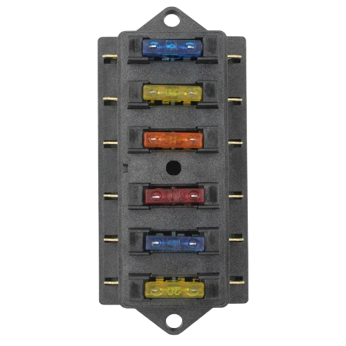
A 6-way fuse box is an essential electrical component designed to house and organize up to six fuses. It provides a centralized location for protecting multiple circuits within a system, ensuring safety and preventing damage caused by overcurrent or short circuits. This component is widely used in automotive, marine, and industrial applications, as well as in DIY electronics projects, where multiple circuits require individual protection.
Explore Projects Built with 6-Way Fuse Box


Explore Projects Built with 6-Way Fuse Box
Common Applications and Use Cases
- Automotive wiring systems (e.g., cars, trucks, RVs)
- Marine electrical systems (e.g., boats, yachts)
- Industrial control panels
- Home or DIY electronics projects
- Solar power systems for circuit protection
Technical Specifications
Below are the key technical details of a typical 6-way fuse box:
| Specification | Details |
|---|---|
| Number of Circuits | 6 |
| Fuse Type | Standard blade fuses (e.g., ATC/ATO) |
| Voltage Rating | 12V to 32V DC |
| Maximum Current | 30A per circuit (varies by model) |
| Material | Flame-retardant plastic housing |
| Input Connection | Single power input terminal |
| Output Connections | 6 individual output terminals |
| Indicator LEDs | Optional (indicates blown fuses) |
| Mounting | Screw or snap-in mounting options |
Pin Configuration and Descriptions
The 6-way fuse box typically has the following connections:
| Pin/Terminal | Description |
|---|---|
| Power Input | Connects to the positive terminal of the power source. |
| Ground | Connects to the negative terminal or chassis ground. |
| Fuse Slots (1-6) | Houses individual fuses for each circuit. |
| Output Terminals (1-6) | Provides power to the connected circuits. |
Usage Instructions
How to Use the 6-Way Fuse Box in a Circuit
- Mount the Fuse Box: Secure the fuse box in a convenient and accessible location using screws or a mounting bracket.
- Connect the Power Input: Attach the positive wire from the power source (e.g., battery) to the power input terminal of the fuse box.
- Connect the Ground: Attach the negative wire from the power source to the ground terminal of the fuse box.
- Insert Fuses: Insert the appropriate blade fuses into the fuse slots. Ensure the fuse ratings match the current requirements of the connected circuits.
- Connect the Circuits: Attach the positive wires of the circuits to the output terminals of the fuse box. The negative wires of the circuits should be connected to a common ground.
- Test the System: Power on the system and verify that all circuits are functioning correctly. Check the indicator LEDs (if available) to ensure no fuses are blown.
Important Considerations and Best Practices
- Fuse Ratings: Always use fuses with the correct current rating for each circuit. Using a fuse with a higher rating than required can lead to circuit damage.
- Wire Gauge: Use wires with an appropriate gauge to handle the current load of each circuit.
- Secure Connections: Ensure all connections are tight and secure to prevent loose wires or arcing.
- Indicator LEDs: If the fuse box includes indicator LEDs, check them regularly to identify blown fuses quickly.
- Environment: Install the fuse box in a dry, well-ventilated area to prevent moisture or corrosion.
Example: Connecting to an Arduino UNO
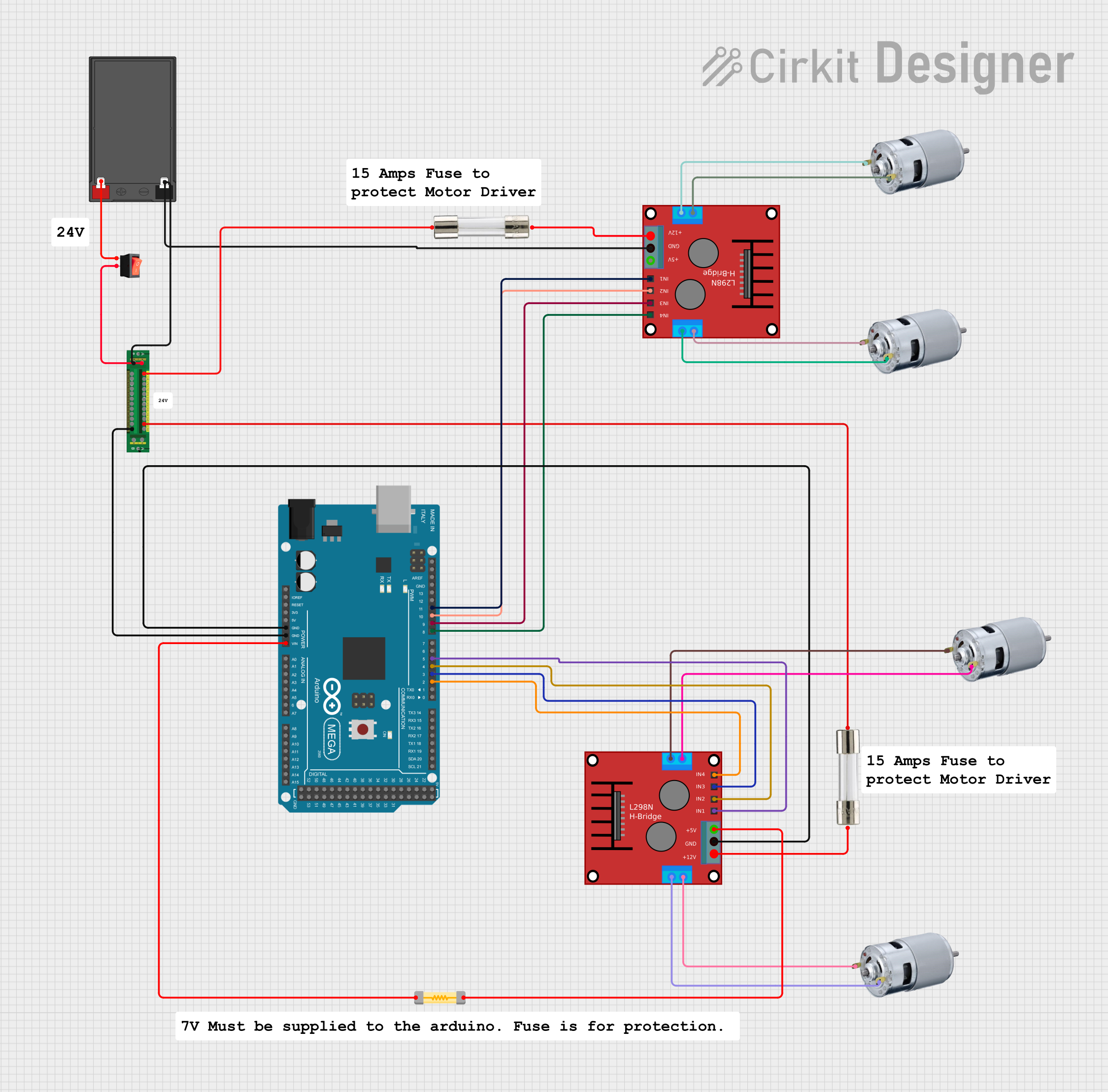
A 6-way fuse box can be used to protect multiple circuits in an Arduino-based project. Below is an example of how to connect the fuse box to an Arduino-powered system:
- Connect the power input terminal of the fuse box to a 12V DC power source.
- Use one of the output terminals to power the Arduino UNO via its VIN pin.
- Use additional output terminals to power other components, such as sensors or motors, with appropriate fuses for each circuit.
// Example Arduino code for a project using a 6-way fuse box
// This code blinks an LED connected to pin 13

void setup() {
  pinMode(13, OUTPUT); // Set pin 13 as an output for the LED
}

void loop() {
  digitalWrite(13, HIGH); // Turn the LED on
  delay(1000);            // Wait for 1 second
  digitalWrite(13, LOW);  // Turn the LED off
  delay(1000);            // Wait for 1 second
}
Troubleshooting and FAQs
Common Issues and Solutions
| Issue | Solution |
|---|---|
| Fuse keeps blowing | Check for short circuits or excessive current draw in the connected circuit. |
| No power to circuits | Verify the power input and ground connections. Ensure the fuse is not blown. |
| Indicator LED not working | Ensure the LED is functional and properly connected (if applicable). |
| Loose connections | Tighten all terminal screws and check for secure wire connections. |
| Corrosion on terminals | Clean the terminals and apply dielectric grease to prevent future corrosion. |
FAQs
Can I use the fuse box for AC circuits?
- No, this fuse box is designed for DC circuits only, typically within a 12V to 32V range.
What happens if I use a fuse with a higher rating than required?
- Using a higher-rated fuse can prevent it from blowing during an overcurrent situation, potentially damaging the circuit or connected devices.
Can I connect multiple circuits to a single output terminal?
- It is not recommended, as this can lead to overloading the fuse and may cause uneven current distribution.
How do I know which fuse is blown?
- If the fuse box includes indicator LEDs, the LED corresponding to the blown fuse will light up. Otherwise, you can visually inspect the fuses or use a multimeter to check continuity.
By following this documentation, you can safely and effectively use a 6-way fuse box in your electrical projects.